DIYM Open Resin Tests
Details of how we test Resin 3D Printers.
Welcome to the 'DIYM Open Resin Test' part of the DIY Machine's Open Testing Framework (OTF). You can find more about the Framework as a whole on the main Testing page here.
This page will detail the testing process as designed for resin based 3D printers. As with all aspects of the DIYM Open Testing Framework I strongly encourage feedback.
If you have any input on the implementation of the testing process, or believe something is missing or superfluous then please do get in touch and let me know. I want to work with the wider maker community to make this the best and most useful it can be.
Please leave any comments, ideas, or advice on the Open Testing Framework Discord Channel:https://discord.gg/JfEPGH8CDt
If you use this framework for your review (which you are encouraged to do) please include a link to it in your documentation/video and a mention. The more who know about / use it the better it will become over time. Thank you.
An example of the DIYM Open Resin Test
This video uses the first iteration of the DIYM Open Resin Test to put the Creality Halot-X1 through its paces whilst introducing the testing standard.
Below this, we will no go though step-by-step how to repeat the tests shown in the video. Required 3D printable files for the test prints along with any other resources needed to replicate the tests will be included at the relevant step.
So what is this test? It separates into three main categorise. The first and last are mostly qualitative in their findings whereas the second section on Dimensional Accuracy & Fine Detail focuses on quantitative tests. As such, this is what we will cover mostly later in this guide:
The "Out-of-Box" Experience:
Our first testing starts before we’ve even powered it on. We’ll look at how much friction exists between the box and your first successful print whilst considering build quality, levelling system, vat design, set-up and more.
Dimensional Accuracy & Fine Detail
This is where we focus on the more technical details and get into the nitty gritty; print resolution, z-performace, surface quality, dimensional accuracy, light uniformity, speed, noise and more. My goal in this section is to create tests that result in numerical answers - the less ‘opinion’ that’s needed the more consistency these tests will have across many printers across many years and perhaps many reviewers.
This consistency of the tests is what I’m really focusing on here. Once I’ve subjected several machines to this same suite of torture I will publicly publish all the data onto DIY Machines’ website where you can freely compare several printers side-by-side to help you make as an informed decision as possible.
Software and Workflow
A printer is nothing without its slicer. We will check if it forces you to use a clunky "in-house" slicer, or is it more open and compatible with programs like Lychee or ChituBox? And Does the Wi-Fi actually work, or are you stuck shuffling a USB stick back and forth like it's 2005?
As more printers include remote monitoring features, we’ll consider if any included cameras are useful along with; smart notifications, power recovery behaviour etc.
Introduction to the tests:
We will work through 8 tests each designed measure as many difference performance metrics as possible.
To keep this testing fair over several machines we also need to standardise the Resin being used to remove as many variables as is comfortably possible. I have chosen Elegoo’s 8k ABS-Like 3D 3.0 Resin in a Clay like colour for better visibility. The resin will always be thoroughly mixed in the bottle and poured in before each print after being warmed to 20º, the room will be maintained as close to 20º as possible throughout the print duration.
I have dialled in this resin by working through two visual calibration models. The first is the Resin Validation Matrix by Tyler Schubert, and then the Siraya Tech Resin Test. I then also set up Shrinking Compensation in the Chitubox using Jan Mrázek’s models and guide before reconfirming the two visual calibration models one more time.
https://www.printables.com/model/229429-photonsters-validation-matrix-v2
https://blog.honzamrazek.cz/2022/06/getting-perfectly-crisp-and-dimensionally-accurate-3d-prints-on-a-resin-printer-fighting-resin-shrinkage-and-exposure-bleeding/
Each print will be allowed to drip dry first, before being pre-washed in one alcohol bath by hand, then washed in the wash station. After allowing it to air dry the part will then be cured in two different orientations, each time for 3.5 minutes. Any support structures will be removed after washing but before curing.
To account for the continued resin shrinkage that occurs in the printed test models both during the initial curing by the printer, and then with secondary curing in the UV curing station and ongoing polymerisation for a period of time afterwards - all test prints are left for 24 hours before being assessed.
Penalty Points will be assigned at each test. So the lower the point score at the end - the better the machine performed.
The first three tests concern themselves with printers ability to reproduce geometric features faithfully into the real world.
Test 1: Dimensional Accuracy
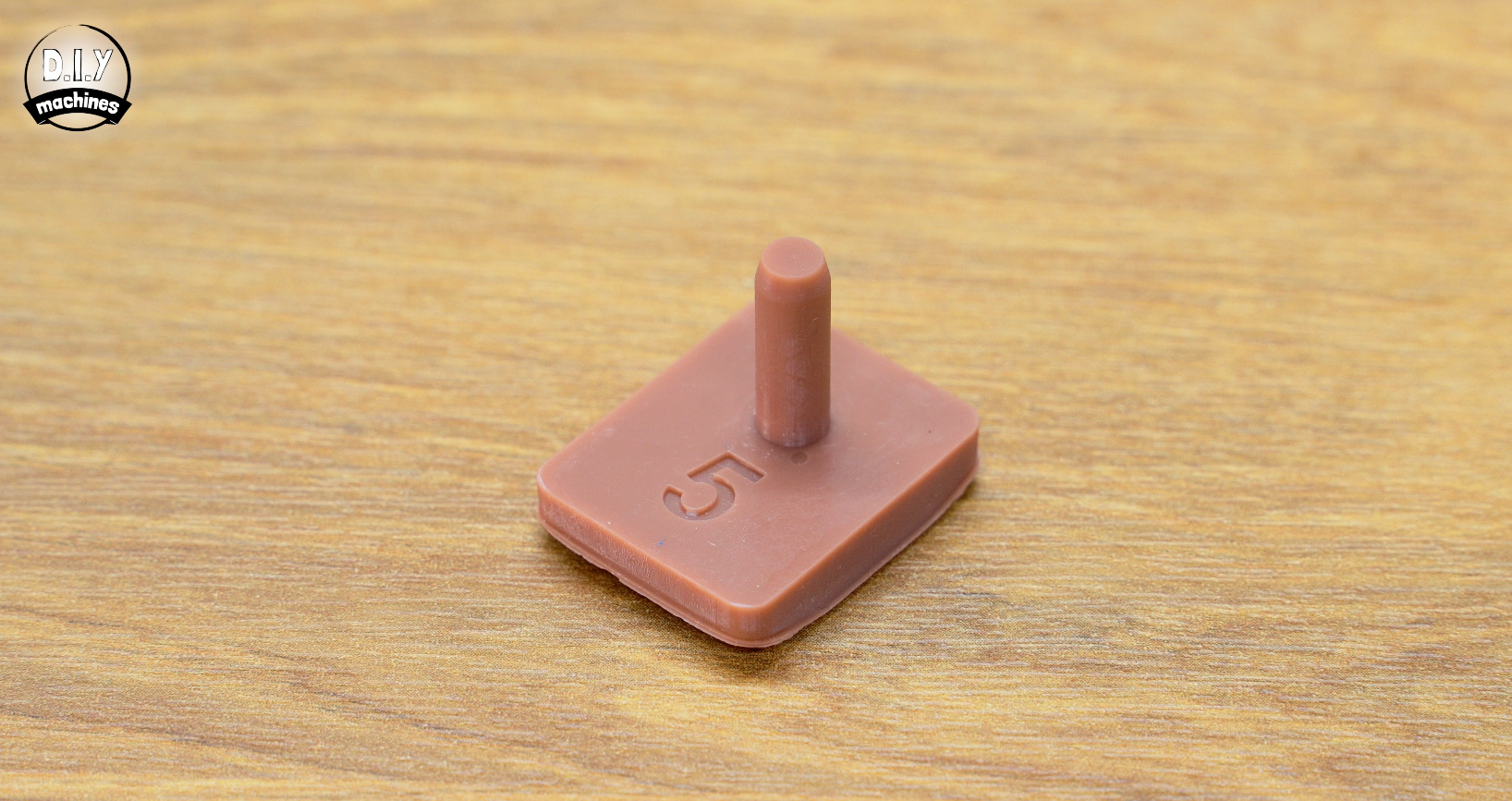
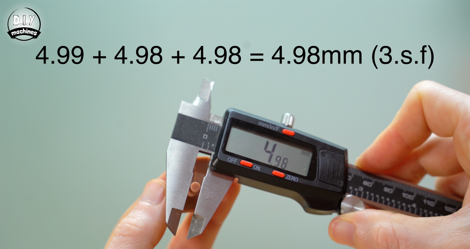
For this step we will print a pin with an expected diameter of 5mm. (Digital model file for printing attached below). Using an accurate digital caliper, take three measurements across different sections of the printed pin. Calculate an average of those measurements.
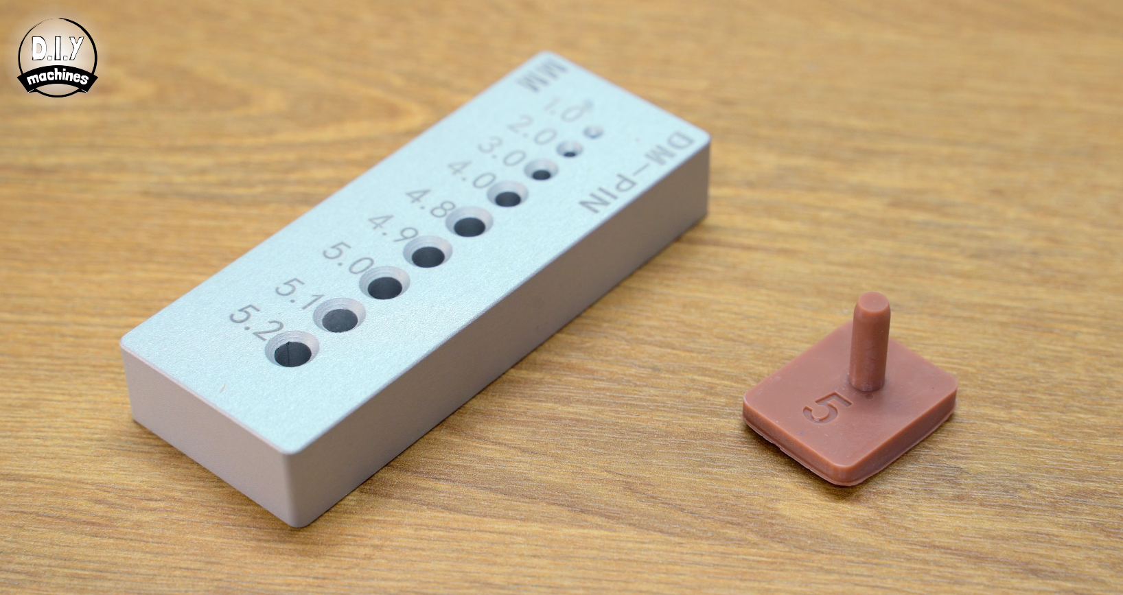
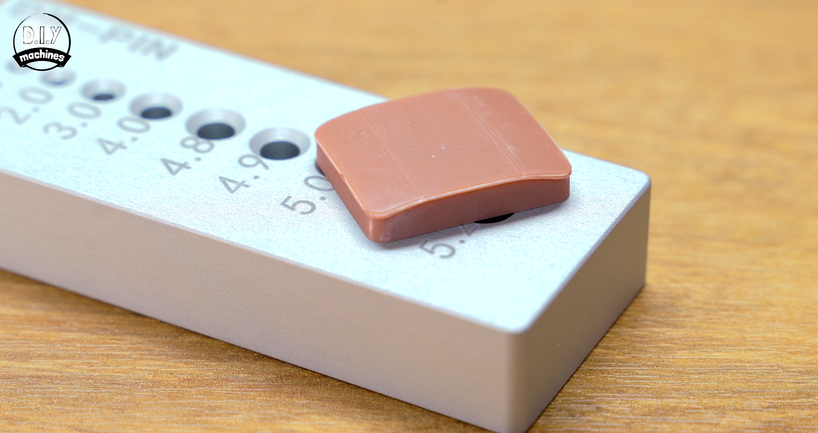
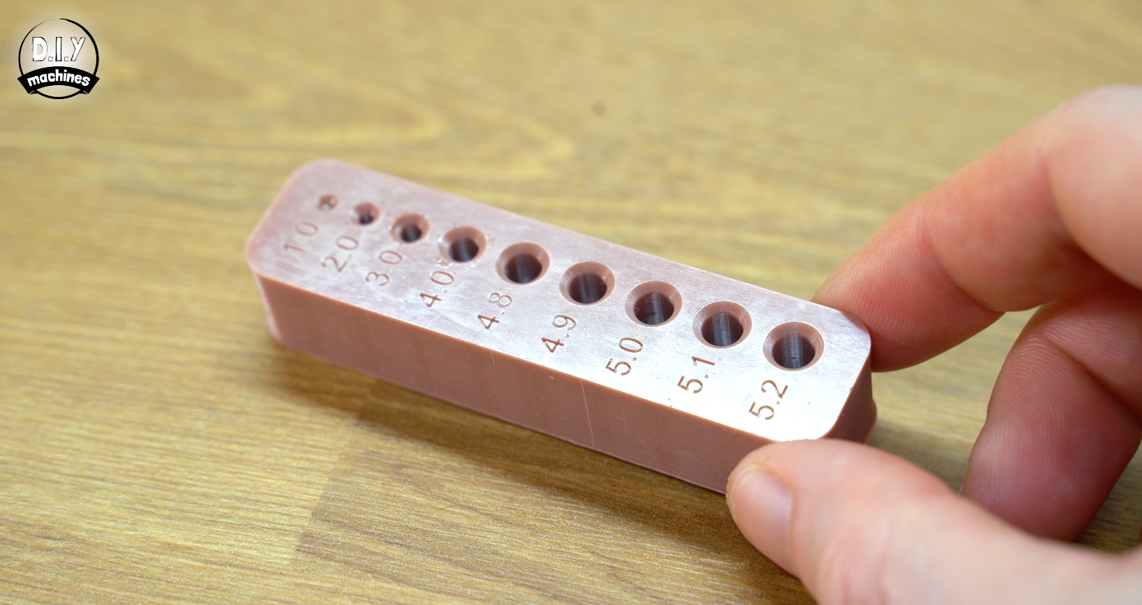
I also had PCBWay manufacture a testing block from aluminium with tight restrictions on tolerances. This block has a selection of holes machines in it and serves as an additional check across the full length of the pin. The printed pin is tested in each of the holes from the smallest to the largest until it fit's in along it's full length. We expect a printed 5mm pin should not fit the 5mm hole, but should fit in the 5.1mm hole.
Penalty points: 1 point for each 0.01mm away from 5mm for the printed pins caliper measurement and 5 points for each 0.1mm away from the 5.1mm aluminium hole being the best fit.
Test 2: Whole Test
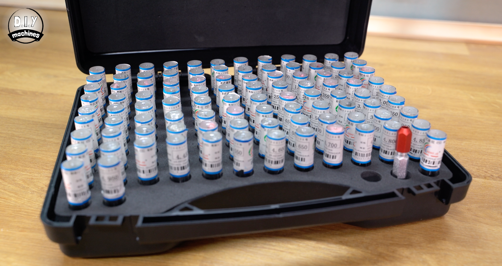
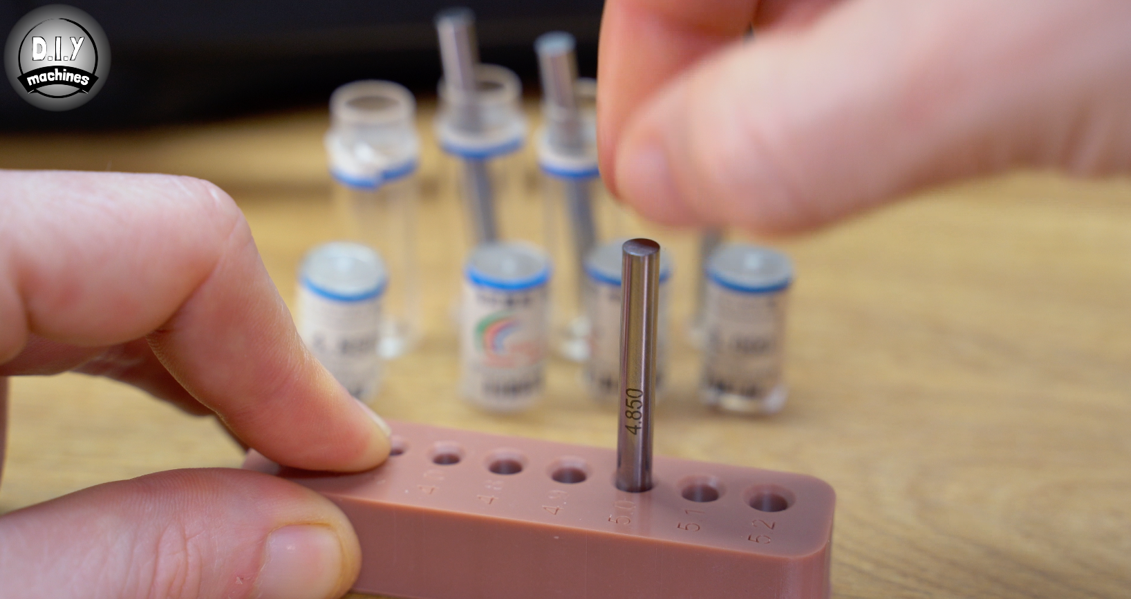
For this test we 3D print a block and then used a set of precision pin gauges to find the largest size we could fit in the 5mm printed hole.
Penalty points:
2 points for each 0.05mm away from 4.95mm pin being best fit.
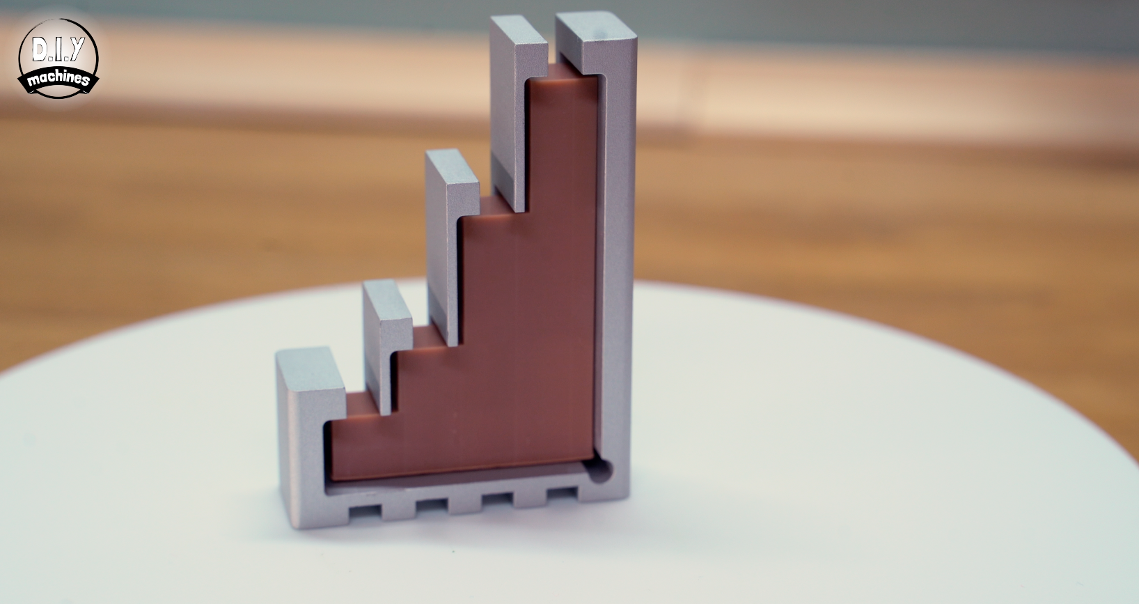
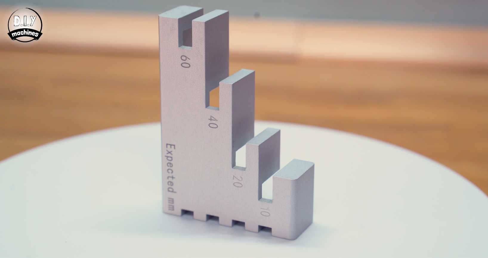
Test 3: Z-Squish
This time we’re looking at any presence of Z squish and elephants foot to measure how much the first few layers of a print are being compressed or over-expanded. As we usually over-expose the bottom layers to make sure they stick to the build plate, the resin can "bleed" outward, and the physical pressure of the build plate against the FEP film can actually shorten the vertical height of your model.
To test this we print a stair-like piece with 4 points to measure. To help with consistent measurements over many printer tests I created an aluminium guide with PCBWay, this ensures that my calibers are taking a measurement down the centre of each column thanks to these locating notches. (Again, aiming for consistency over many tests).
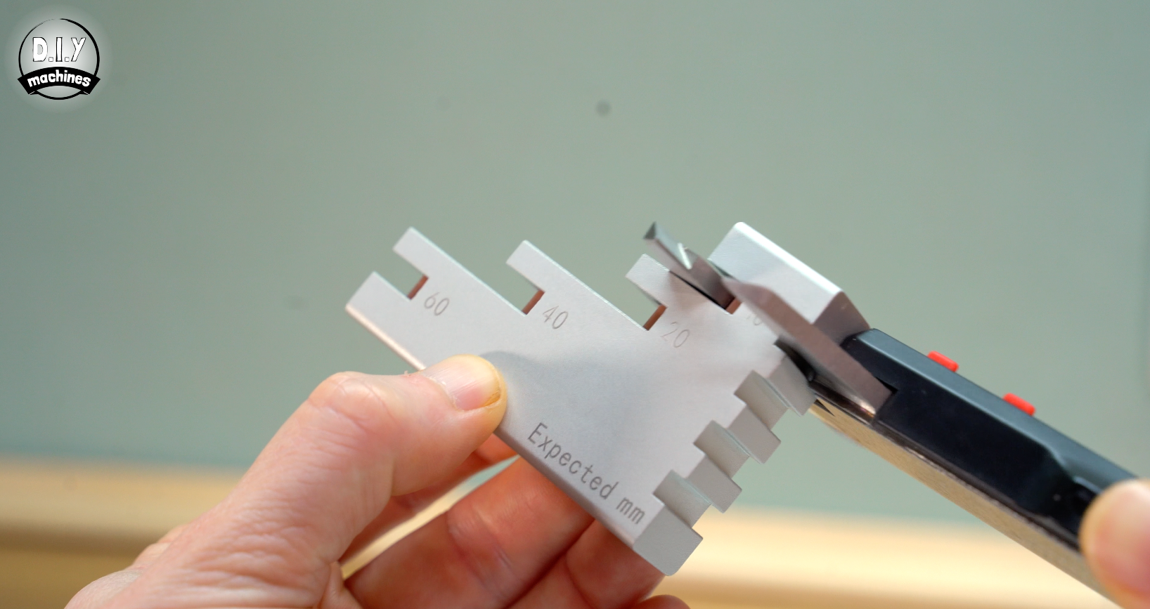
Penalty Points:
Here points are calculated by adding up the variance and then multiplying by 5 and rounding to the nearest whole number.
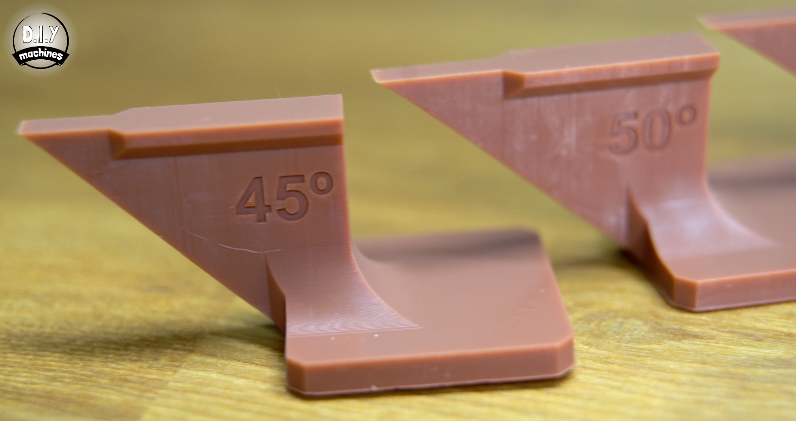
Test 4: Overhang Ability
In resin printing, every layer is a tug-of-war between the build plate and the vat film. The ability of the printer to successfully print a overhang relies on several factors, so though this test does not target any specific area it does reveal how well they work in combination to achieve this test part.
Success depends on how well the printer manages the "Peel Force"—that physical suction created when the printer tries to pull a newly cured, delicate layer off the bottom of the tank. Consistent mechanical movements on the Z-Axis & decent Step Precision also play a role.
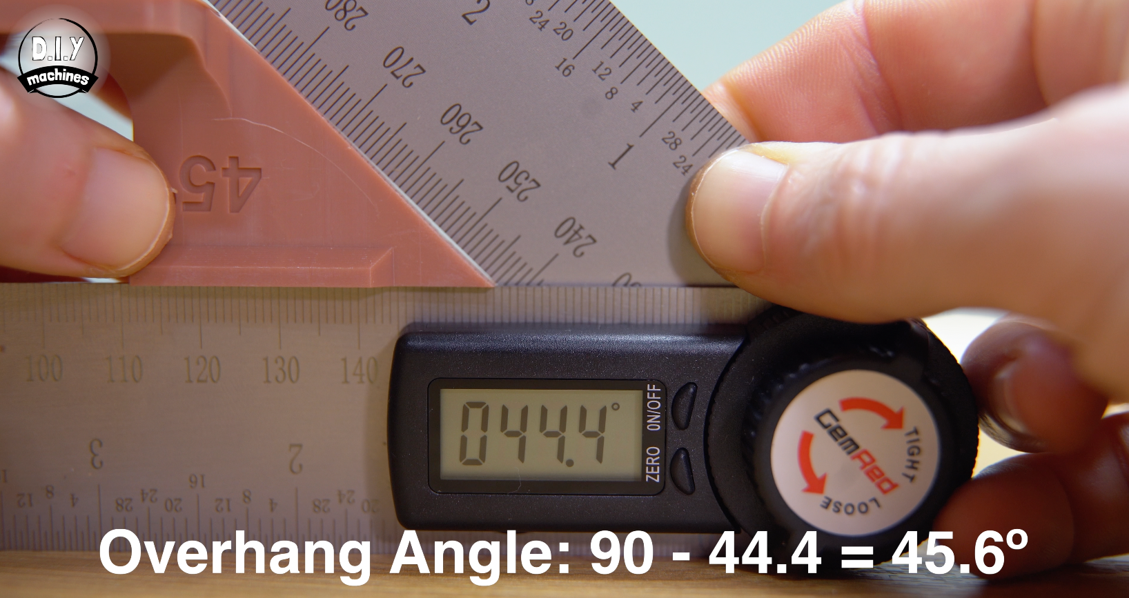
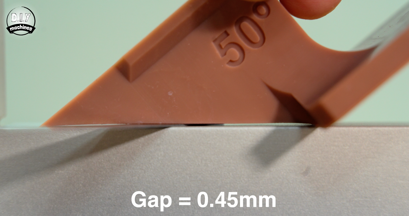
Testing this involves printing a set of overhang blocks and then measuring the actually printed overhang angle and checking for straightness along the length of the overhang. Measuring for the overhang angle was done using a Digital Protractor taking a measurement from the base of the overhang to the tip.
Penalty Points:
Here points are calculated by adding up the variance and then multiplying by 5 and rounding to the nearest whole number.
An overhang can be at the "correct" angle but still be "bowed" or "wavy" due to suction forces during the peel cycle so to measure the maximum deviation between these two points I used a set of feeler gauges to find the largest gap along the length of the overhangs edge for each of the printed tests.
Penalty Points: For the angles, penalty points are calculated by adding up the difference from perfect and then multiplying by 5 and rounding to the nearest whole number.
Test 5: Overall replication test
Using a resin printer to print models such as the demo models provided by the manufacturer , or other miniature characters is a very common use for resin printers. So I decided to include an overall replication test by printing a Groot model, then using a 3D scanner and turntable to capture the printed model back into the computer and then used CloudCompute to calculate the difference between the model we sent to the slicer and the model the printer actually created.
To do this I used the RevoPoint Metro Y Pro scanner. To improve the accuracy of the scan I also applied a Sublimating spray to the model. This means it evaporates away by itself after around 6 to 24 hours, no cleaning required. It creates a matt surface on the model with a roughly 6.5µm coating which preserves the models details and dimensions.
The turntable takes care of capturing plenty of scans from all around the model and at multiple angles.
Once completed we load both the 3D scanned model and the original STL file into the Open Source CloudCompare software. The two models have their scale and orientation matched before we have the software calculate both a mean distance between the models and standard deviation figure.
Penalty Points: Multiply Standard Deviation by 2 and add this to Mean Distance multiplied by 100 and rounded to nearest whole.
Test 6: Light Uniformity
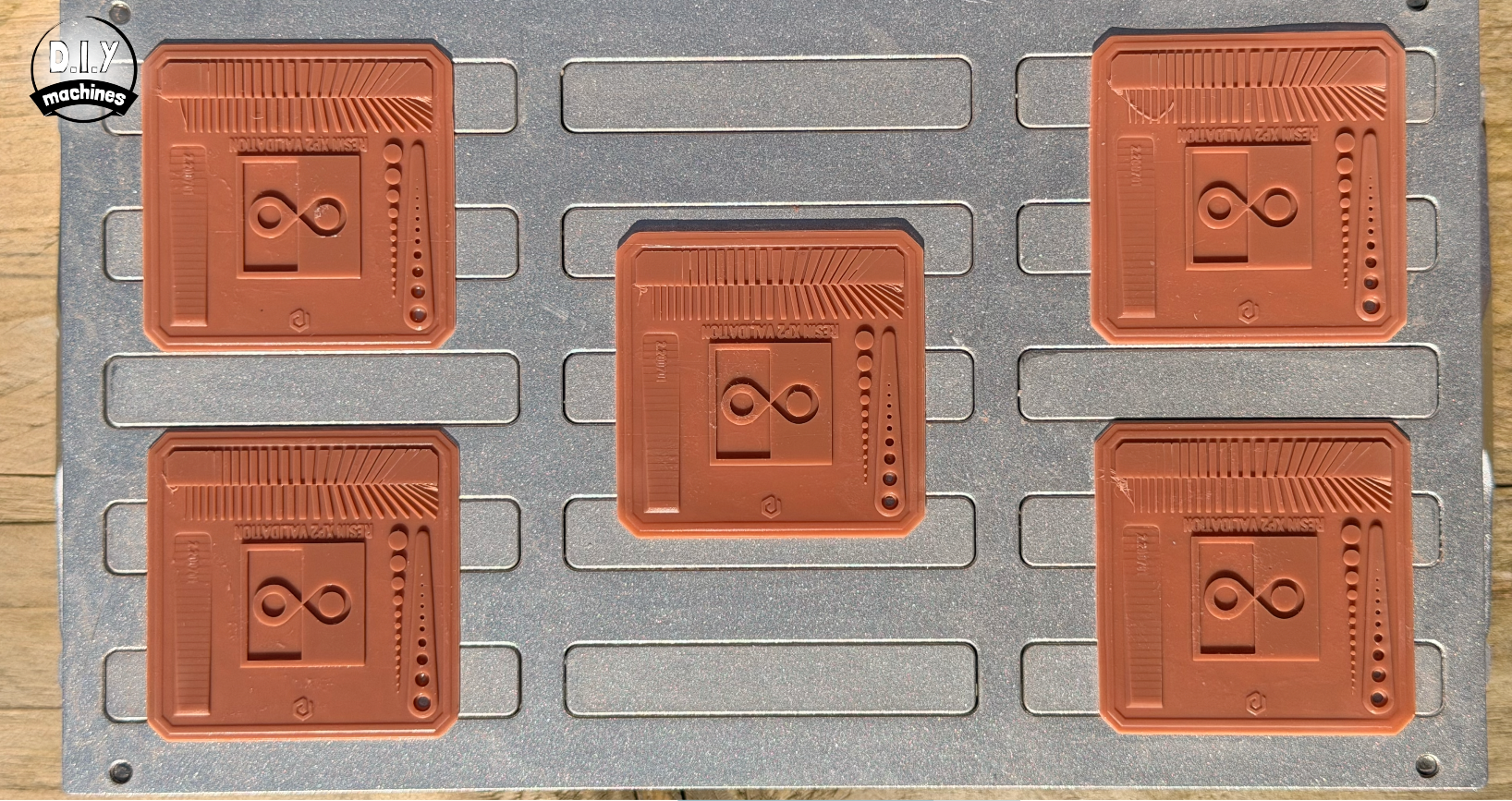
This test measures how evenly UV light is distributed across the resin printer's screen. In a perfect world, every pixel would receive the exact same intensity of light, but in reality, the centre is often brighter than the corners.
If your light uniformity is poor, a model that prints perfectly in the centre might fail or lose detail when moved to the edge of the build plate.
To test this we will print five more resin test prints, one in the centre and one in each of the four corners. These should then be prepared by washing in-situ and then allowed to fully dry.
Test print used:
https://siraya.tech/pages/siraya-tech-test-model?srsltid=AfmBOoqKe0Q8gwxhzTOtBKNugoPGG2fmY9WChLp207E6WumVm922xcTv
Penalty points: Based on how many features where shown on the centre model, and then give a point for each additional or fewer features shown on the models printed in the four corners.
Test 7: Squareness
You might wonder, ‘Do we actually need to test for this?’, because the X and Y coordinates are effectively "baked" into the physical pixel grid of the LCD screen, The angle between the rows and columns of pixels is physically fixed at 90º. Unlike an FDM printer, which relies on two independent moving gantries (which can be physically out of square), an MSLA printer has no X/Y motion.
So if the screen was simply rotated during manufacturing relative to the printer frame this would not result in a skewed or rhombus-shaped print. It will just result in a square print that is sitting crooked on the build plate.
However, there are other factors that can effect the squareness of the print like Optical Keystoning and Z-Axis Lean.
In some MSLA printers with poorly aligned light engines, the light source might not be perfectly perpendicular to the screen. If the light hits the LCD at an angle, it creates Keystone Distortion.
This stretches one side of the print more than the other, turning your square into a trapezoid.
While the pixels on the screen are square, the "shadows" they cast into the resin are distorted by the angle of the light.
As for the Z-Axis Lean - this is the most common form of "skew" people report in resin printing and it isn't actually in the X/Y plane; it’s Z-axis skew.
If your Z-rail is not perfectly 90∘ to the LCD screen, your vertical walls will lean. In this case, the top of your cube will be shifted relative to the bottom, making the side faces parallelograms.
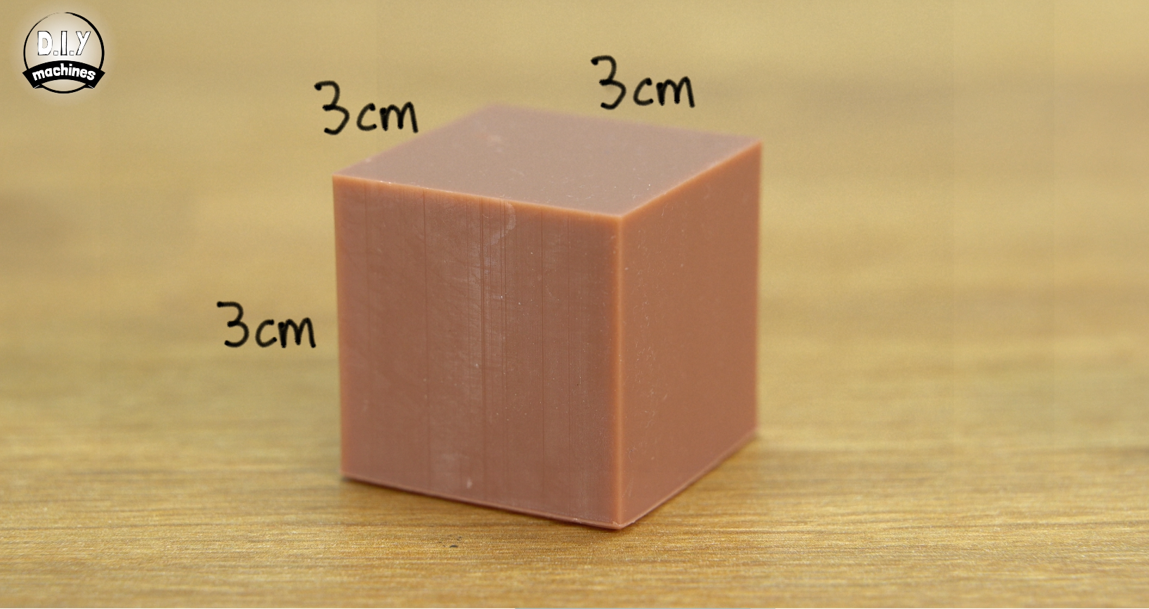
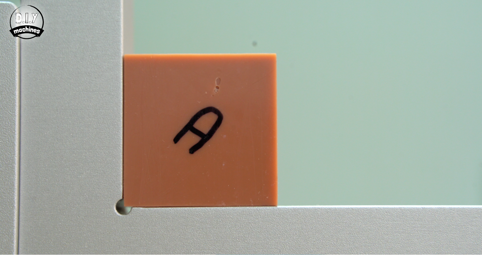
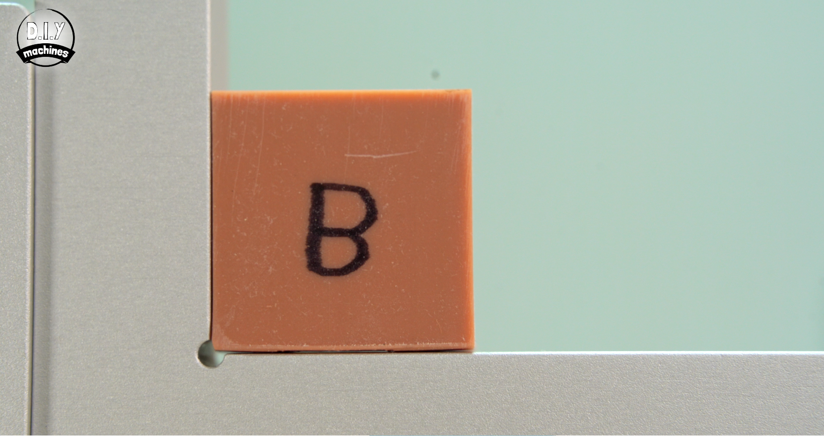
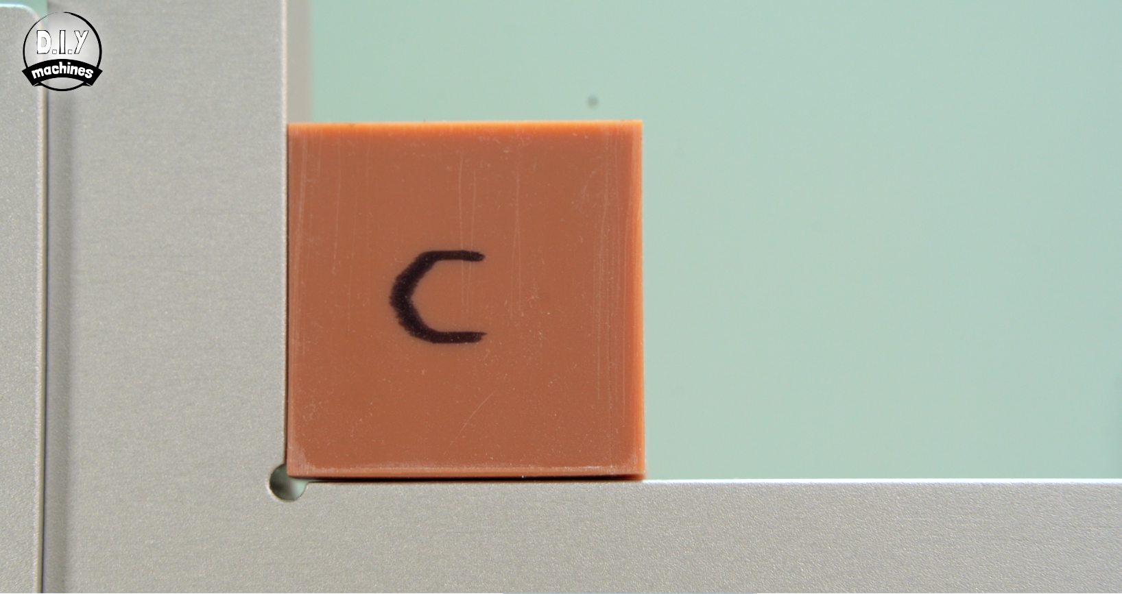
The most reliable way to check for squareness without specialised tools is to print a cube. This one is 3cm cubed, and then measure the diagonals of each face. If the diagonals are equal, the corners are 90°. If you have some slight elephants foot it’s ok to sand it away lightly to bring the walls of the cube to flat.
For a perfect 30mm x 30mm square, the diagonal should be exactly 42.43mm. So we measure from the top left corner to the bottom right, then top right to bottom left for all three planes, the front, top and side.
Penalty points: Any deviation from 42.43mm in the measurements is added up and then multiplied by 4 and rounded to the nearest integer.
As an additional visual check we can also place the cube up against a known perpendicular L-profile. Ideally this should include a small notch to help avoid any elephants foot from interfering with the test. With a bright light behind it we can see any gaps in the model. Photo's of this test should be included in the machines review online for visual comparisons with other machines.