How to Build a Giant Hidden Shelf Edge Clock
We had a large space on part of our living room wall for which we could never find the right 'thing' to hang on it. After trying for several years we decided to make something of our own. This turned out rather well (in our opinion) so I turned it into a project on my Youtube channel and a written a guide which you're reading right now!
It's a giant digital LED clock discreetly hidden in the edges of a geometric shelving system. It also included integrated LED downlighters to show off your favorite items on the shelves.
As the lighting is LED (using WS2821B 'Neopixels') you can choose your own colours - both for the clock face and downlighters. A discreet photoresistor is hidden in the top right corner which dims the LED's when the ambient light levels drop - great for evening ambiance in any room.
DISCORD server: https://discord.gg/EhqqePPcKk
Supplies:
You will need some supplies to build one of your own. Below are links to where you can find the parts on Amazon.
As an Amazon Associate I earn from qualifying purchases.
■ An Arduino Nano(x1): https://geni.us/ArduinoNanoV3
■ A 5m roll of WS2812B LEDS which has 60 LED’s a meter: https://geni.us/5mWS2812B60m
■ A Photosensitive resistor module: https://geni.us/PhotoresistorModule
■ A DS3231: https://geni.us/DS3231-RTC
■ Some Hookup wire - ideally three different colours: https://geni.us/22AWGWire
■ A couple of 470 Ohm resistors: https://geni.us/Ufa2s
■ A couple of electric terminal block strips - each 5 blocks long: https://geni.us/TerminalBlocks
■ No 8 wood screws: https://geni.us/No8Screw
■ A 5v power supply with screw terminals: https://geni.us/PowerSupplyTerm
■ Some thicker twin core cable
■ Some filament for the 3D printed parts: https://geni.us/PLAFilament
■ Wood infused PLA filament: https://geni.us/WoodPLA
■ Wooden backboard at least 112 x 39cm the one I used was 138 x 60cm (this will give the finished project a 10cm border around the outside).
Code and other downloads
Code for the project can be found on its Github page: https://github.com/DIY-Machines/DigitalClockSmartShelving
3D printed parts and wiring diagrams can be downloaded from here: https://www.prusaprinters.org/prints/94364
Drawing for CNC drilling of the backboard (if you have access to a CNC machine or know someone else who does):
https://www.etsy.com/uk/DIYMachines/listing/1081760909
DISCORD server: https://discord.gg/EhqqePPcKk
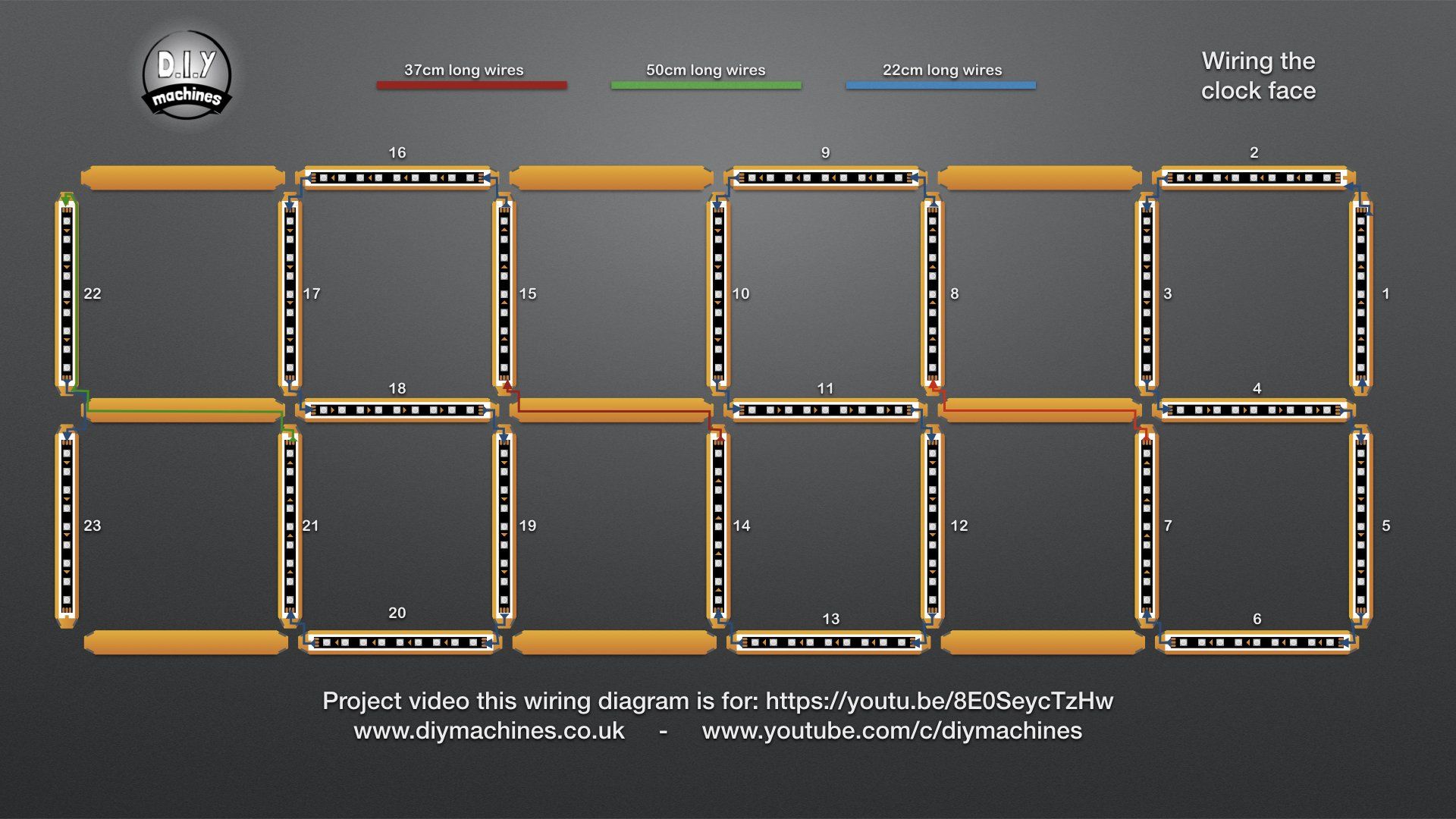
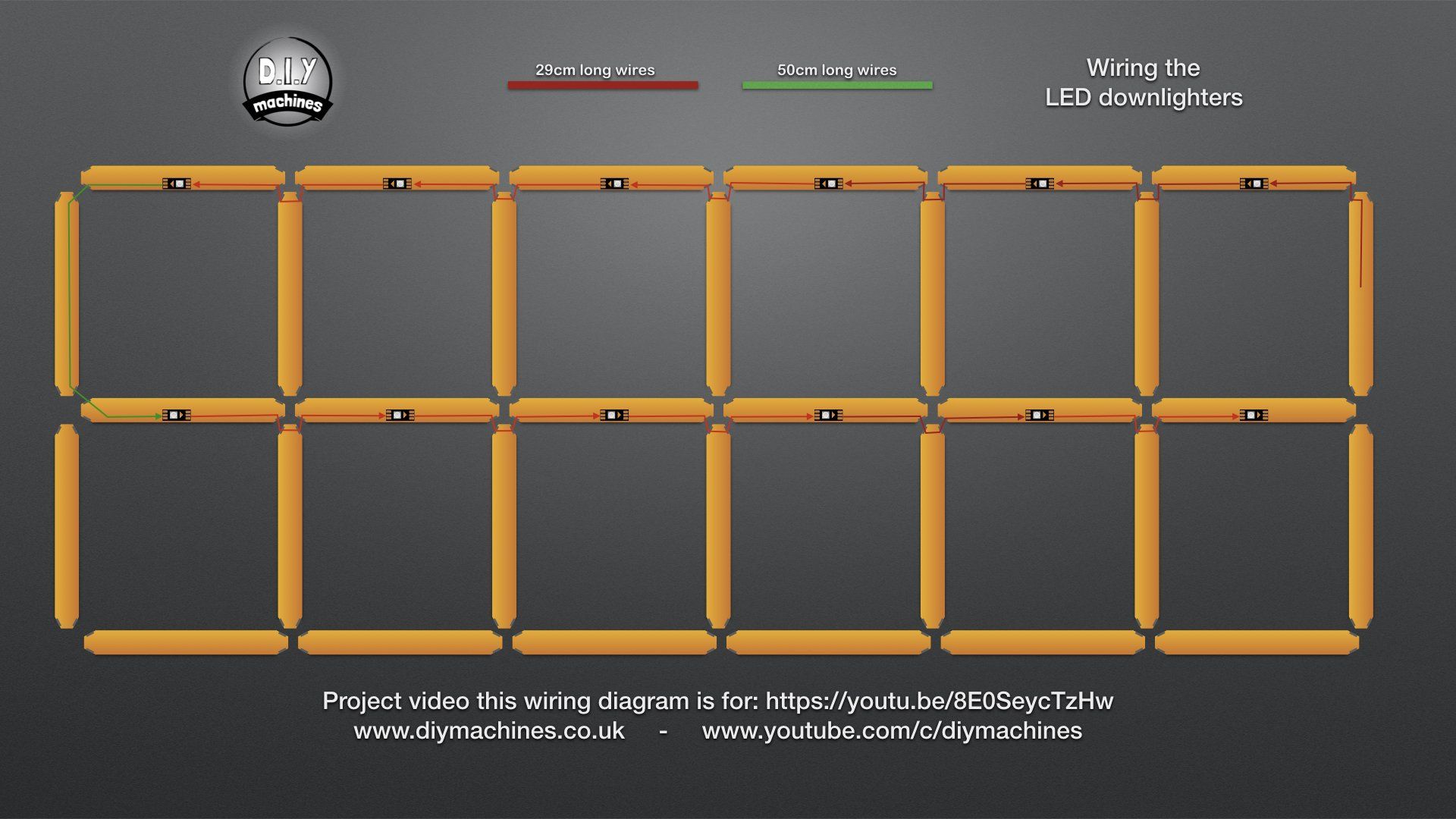
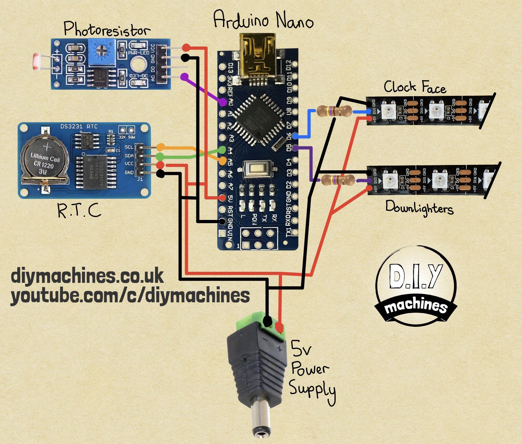
Wiring Diagrams
Click on an image to see a larger version.
FAQ's
Comments