Sensorless Homing with RP2040 & TMC2209
Introduction
In this video, I’ll show you how to set up sensorless homing using a TMC2209 stepper driver — no mechanical limit switches required! Perfect for 3D printers, CNC machines, robotics, and other DIY electronics projects. I’ll guide you through the wiring, Arduino code, and how to tune StallGuard for accurate, reliable homing. Whether you’re building a CoreXY, a custom motion control system, or just want to learn more about stepper motor drivers, this is a great place to start. Let’s build smarter!
Why would we want to use sensorless homing? Well first the Pros…. There’s no need for extra mounts, additional components or running long dangling cables to one or both ends of the carriage or other moving component. And there are always cons, so in this case you’ll need a stallguard-capable driver (they cost a little more and are only manufactured by Trinamic) and accuracy isn’t great at slow speeds.
Video
I created a detailed video demonstrating everything I explain on this page. It's very informative and I spent alot of time on it - so you should totally watch it. :)
Parts and Resources (BOM)
I used a variety of resources, and materials to complete this demonstration.
This is a list of the physical items used in this project and where you can source them:
(As an Amazon Associate I earn from qualifying purchases.)
- RP2040-Zero: https://geni.us/Waveshare-RP2040Zero
- Mini560 DC-DC Buck Converter 5v: https://geni.us/Mini560
- BIGTREETECH TMC2209 V1.3: https://geni.us/TMC2209
- Momentary Button: https://geni.us/6x6TactileButton
- 1k Resistor: https://geni.us/Ufa2s
- Sliding Switch: https://geni.us/SlideSwitchSPDT
- Screw Terminal PCB Mount 5mm pitch: https://geni.us/PCBScrewTerminals
- Headers and Pins: https://geni.us/HeadersAndPins
- DC Barrel - PCB Mounted: https://geni.us/DCBarrelPCBMount
- 3D Printer Filament: https://www.3djake.uk
- Some M3x8 bolts: https://geni.us/NutsAndBolt
- 12v Power Supply (2 amp+): https://geni.us/12VPowerSupply2A
For revised circuit design (version 3 as of July 2025) you'll also need:
- Diode 1N5819 (x1): https://geni.us/Diode1N5819
- Electrolytic Capacitor 100µF, 35V, Low ESR (x1): https://geni.us/Capacitor100uF35vESR
And for the software used to communicate with the project and run the demonstration:
- Andrea's Code: https://github.com/AndreaFavero71/stepper_sensorless_homing
- MicroPython 1.24.1: https://micropython.org/download/PIMORONI_TINY2040/
- Thonny Python IDE: https://thonny.org
Stepper Motors Overview & Back EMF
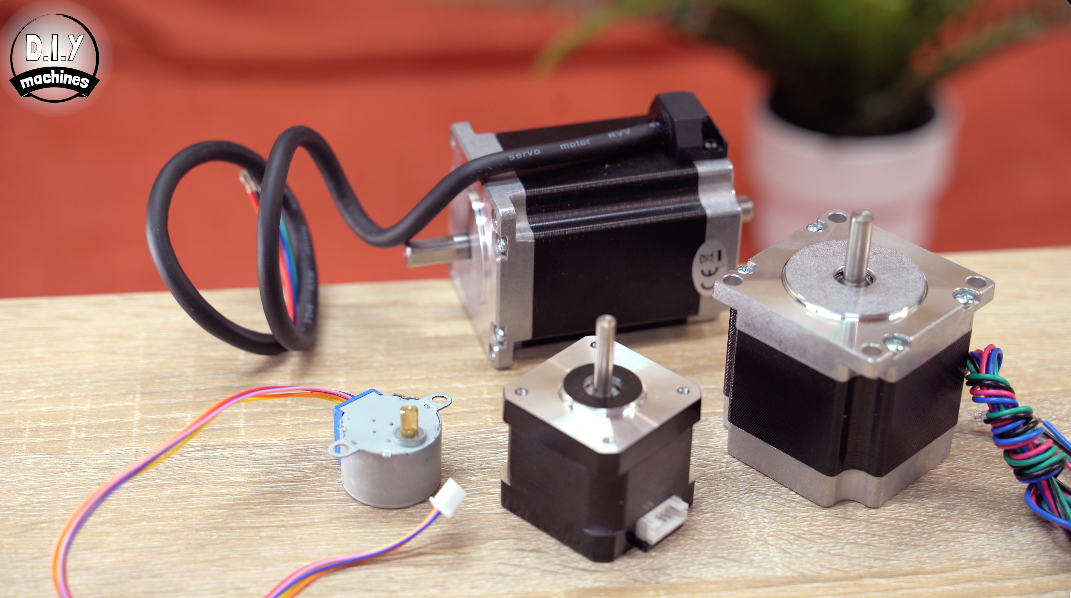
First, let’s quickly go over the basics of a stepper motor as it will help you to understand some of the later concepts. Stepper motors can come in all shapes and sizes
Most stepper motors have around 50 physical teeth on the rotor. The rotor is the rotating part of the motor.
The stationary part — a collection of electromagnets surrounding the rotor — is called the stator. When the stator coils are energised in a controlled sequence, the rotor rotates step by step, locking into a new position with each change in the magnetic field.
Stepper motors generate back-EMF as they move — this will be important later.
Back-EMF is a voltage produced by the motion of the rotor through the motor’s magnetic field. The faster the rotor moves, the more back-EMF is generated.
Some stepper drivers, like the TMC2209, can monitor this using internal current sensing to estimate motor load or detect stalls.
Quick side note on supper motors: They are normally referred to as a ‘NEMA” then a number. Such as NEMA17 or NEMA23. This is not directly linked to the Torque, voltage, current rating, step angle, shaft size or the physical length or depth of the motor. NEMA stands for the National Electrical Manufacturer Association (NEMA) and the number specifies a a faceplate size.
Assembling the Demo Circuit
To recreate this example for yourself we’ll be using just a few parts as listed earlier in these Instructions in the BOM section. I have assembled two versions for you:
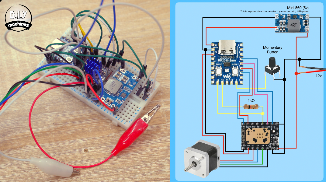
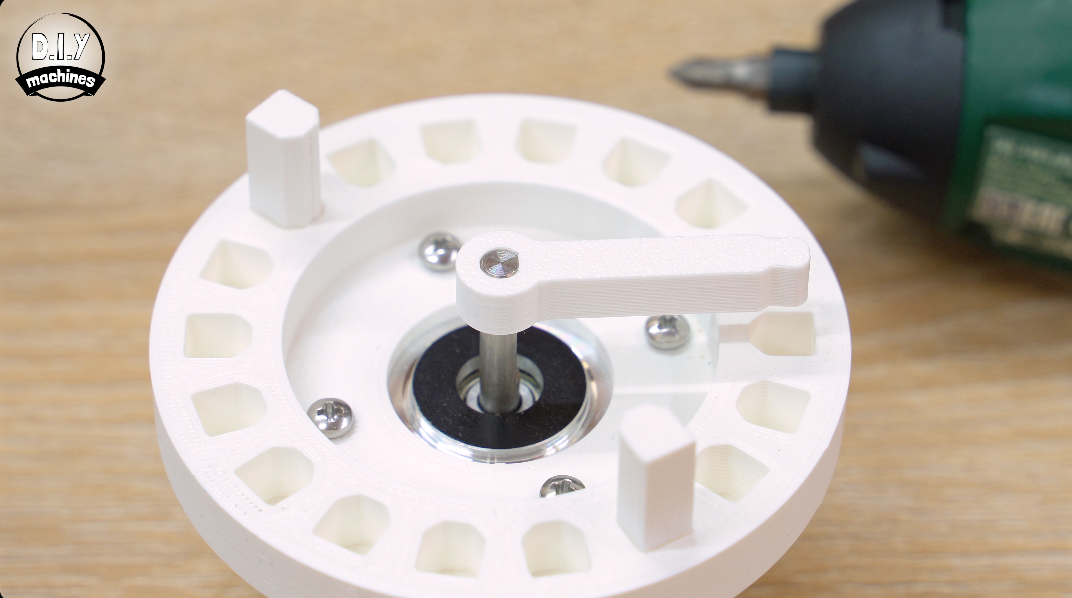
- Using a Breadboard: You can build the circuit on a breadboard following my wiring diagram. To create the stalling condition you can keep it super simple and carefully grab the shaft of the stepper to create resistance or feel free to 3D print the little mount attached to this step which attaches to the motor and let’s you move end stops at will by repositioning the pegs.
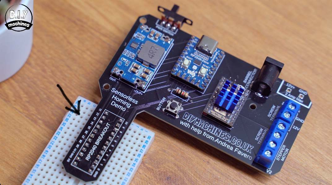
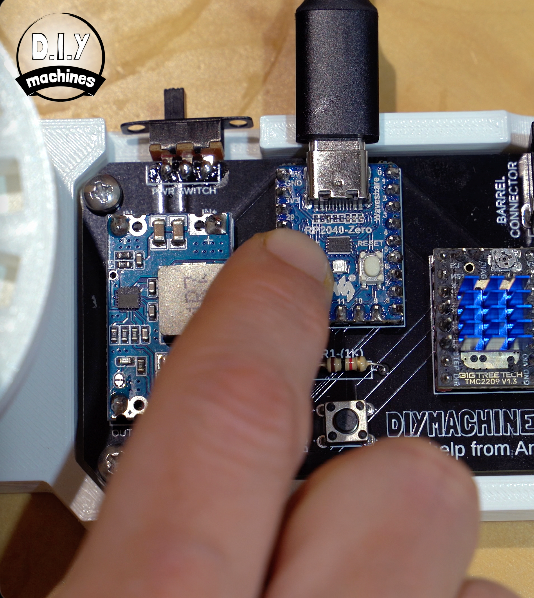
- Use a the PCB: To make things even tidier I’ve created a little PCB design which holds all the components together without a snake pit of wires. Just insert the components where marked and solder in place on the reverse.

The PCB also adds some additional features to help you develop your own project. It allows you to power the circuity with either soldered wires, wires attached with a screw terminal or via a DC barrel.
You’ll also be able to attach a breadboard at the bottom giving you access to all the pins of the RP2040 breakout so you can build your own project on top of Andrea’s software if you wanted to. The DC to DC Buck converter takes the motors supply voltage between 7 to 20v and provides 5v for the microcontroller.
Uploading the Code
Five Python files written by Andrea power the whole demo — let’s go over how to upload them to your RP2040 and walk through the code to help you understand what’s happening.
To follow along, you’ll need to download the free Thonny editor from https://thonny.org and a copy of MicroPython. https://micropython.org/download/ Be sure to download version 1.24.1 of MicroPython.
Andrea's code can be downloaded from Github here: https://github.com/andreafavero71/stepper_sensorless_homing
Preparing the RP2040
To prepare the RP2040, connect it to your PC while holding down both the BOOT and RESET buttons. Once connected, release the RESET button but continue holding BOOT until it mounts as a removable drive on your computer.
Next, drag and drop the MicroPython .uf2 file onto this drive. The RP2040 will then disconnect and automatically install MicroPython. This takes only a few seconds.
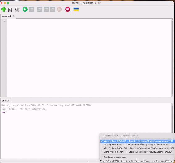
Open the Thonny Editor, and connect to the RP2040 by selecting it from the dropdown menu in the bottom-right corner of the Thonny window.
Now download the five Python files from Andrea’s GitHub repository.
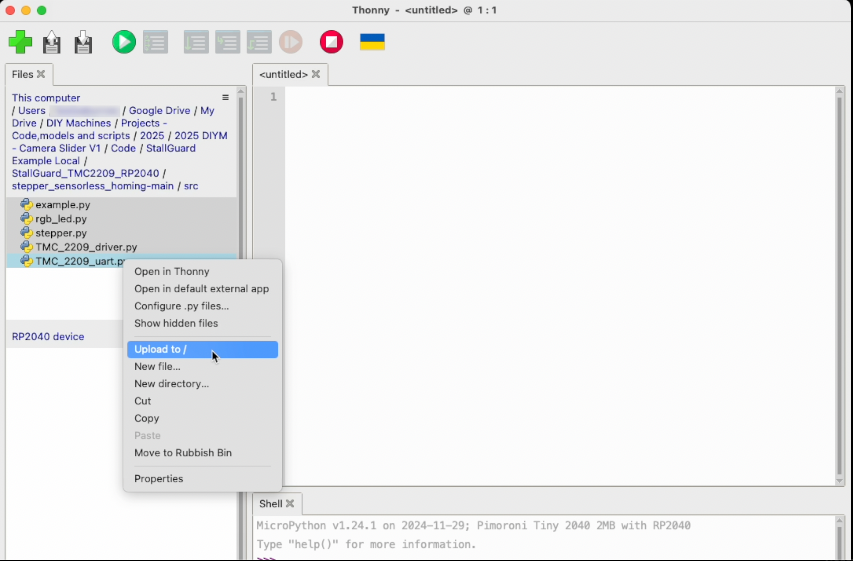
In Thonny, open the Files pane. (On macOS, you’ll find this under the View menu.)
Navigate to your downloaded Python files, select all five, right-click, and choose “Upload to /” to copy them to the RP2040.
Code Overview
Let’s take a high-level look through the five Python files that power this project, so you can understand how they work together.
example.py – The Entry Point
This is the main file and it’s what we run first.
It sets up the hardware: the motor driver, LED, and pushbutton.
It also handles the loop that waits for the button press, and then starts the homing routine.
Think of this as the control hub — the file that brings everything else together and tells it when to run.
⸻⸻⸻⸻⸻⸻⸻⸻⸻
stepper.py – Motor Control & Homing Logic
This file handles everything related to the stepper motor.
The RP4040 microprocessor and it successor (the RP2050), normally used in raspberry Pi Pico’s, has the Programmable Input Output (PIO) feature: In this demo the PIO is used to generate the steps for the stepper, as well as to count steps in between the homes. The PIO are like independent CPUs, therefore helping to avoid overloading the main CPU.
The homing logic lives here also— including how far the motor turns, how stall detection works, and when it decides it has hit an end stop.
This file is also where you can tweak sensitivity values and adjust motion settings.
If something’s not behaving right — this is usually the file you’ll need to edit.
⸻⸻⸻⸻⸻⸻⸻⸻⸻
TMC_2209_driver.py – Talking to the Motor Driver
This file handles UART communication with the TMC2209 stepper driver.
It defines how to send and receive data like speed and StallGuard readings.
It’s responsible for configuring the driver properly — like enabling StallGuard, current settings, and microstepping.
Most users won’t need to edit this file — it’s a low-level helper that just does its job in the background.
⸻⸻⸻⸻⸻⸻⸻⸻⸻
TMC_2209_uart.py – Low-Level UART Details
This is where the raw serial communication logic lives.
It’s a technical file that formats and parses the binary data sent to and from the driver chip.
It deals with things like CRC checks and register addresses.
It’s the kind of file you’d only dig into if you needed to extend functionality or troubleshoot the UART communication directly.
⸻⸻⸻⸻⸻⸻⸻⸻⸻
rgb_led.py – Status LED Control
This file manages the RGB LED.
It lets the code easily set different colours for status updates — like when homing starts, finishes, or fails.
It’s a small utility file but great for giving visual feedback on what the system is doing.
⸻⸻⸻⸻⸻⸻⸻⸻⸻
Summary
So, in short:
- example.py is the main controller.
- stepper.py controls the motor and homing logic.
- TMC_2209_driver.py and TMC_2209_uart.py handle communication with the motor driver.
- rgb_led.py controls the visual feedback.
Together, they make it easy to do sensorless homing — and tweak it to suit your project.
Running the Demo
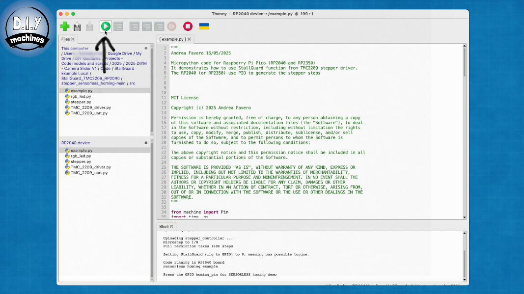
To run the demo code you need to open example.py — making sure that you open the copy located on the RP2040, not the one on your computer — and then click Run current script.
At this point, pressing the physical button on your hardware should trigger the homing routine.
If you want the script to start automatically when the RP2040 power on then we can save a new copy on the device itself and name it main.py. Now when you cycle the power this main.py file runs itself.
Stallguard
StallGuard is a feature of certain Trinamic stepper drivers, like the TMC2209, that can detect when a motor has stalled.
- StallGuard2™: TMC2130, TMC2160, TMC5130, TMC5160, TMC2041
- StallGuard4™: TMC2209, TMC2226
It does this by cleverly sensing and monitoring the back-EMF we mentioned earlier. StallGuard evaluates how much effort (in terms of motor current) is needed to maintain motion and compares this to the expected patterns of back-EMF.
A stall occurs when the rotor can no longer follow the commanded magnetic steps — usually due to mechanical resistance, an obstruction, or too much speed. When this happens, the expected back-EMF pattern drops or becomes unpredictable.
StallGuard detects this change and reacts accordingly:
- The driver calculates a value called SG_RESULT (StallGuard result), which reflects the motor’s load.
- As the load increases — or a stall begins — SG_RESULT decreases.
For our demonstration, we monitor the value of SG_RESULT via Single Wire UART, which is a serial communication method between our microcontroller (the RP2040) and the driver (TMC2209). We will use our own logic to decide if a stall is happening based on the values we see.
Optionally, you can define a threshold in the driver called SGTHRS (StallGuard Threshold). If SG_RESULT drops below this threshold, the TMC2209 will flag a stall on its DIAG pin.
One other value worth knowing is TCOOLTHRS — the velocity threshold. StallGuard only works above this speed. This is because at low speed the back-EMF is too weak to measure reliably.
In short: StallGuard senses how hard your motor is working by watching for changes in back-EMF. If the effort suddenly spikes or the back-EMF drops, the driver assumes the motor is stalling.
Troubleshooting & Tweaks
If your setup doesn’t behave as expected, there are a few parameters in stepper.py that you may need to tweak:
Homing Range
By default, the code allows the motor to turn five full rotations in each direction while searching for end stops. If your motor needs more turns before giving up, increase the value of max_homing_revs on line 115.
StallGuard Sensitivity
On line 341, you’ll find the variable k. Increase this value to make StallGuard more sensitive, or decrease it to reduce sensitivity.
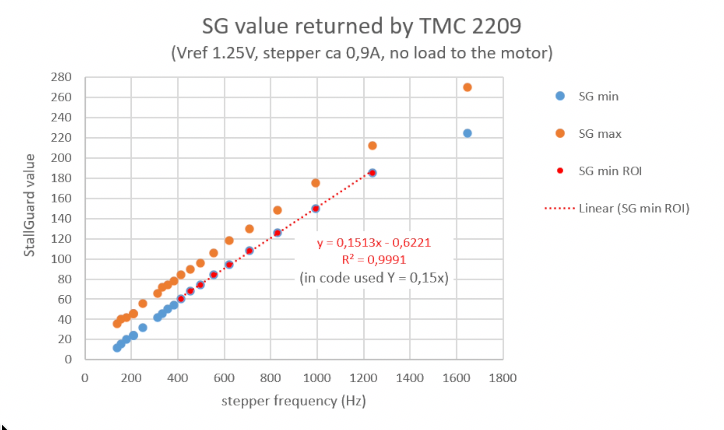
SG Threshold Calculation
On line 340, the SG (StallGuard) threshold is calculated as a function of speed. Andrea derived this from tests where he rotated the motor at various speeds with no load. Since the relationship between StallGuard values and frequency was linear in his data, a slope of 0.15 (the line of best fit) is used to calculate an appropriate SG threshold between 400 Hz and 1200 Hz.
However, your hardware may behave differently, so you may need to experiment with a fixed StallGuard value or create your own function based on your motor’s characteristics.
Comments: