Build Working Stranger Things Walkie-Talkies
I Recreated the Stranger Things Walkie-Talkies (THEY ACTUALLY WORK)
I’ll explain to you how to make your own working replica walkie talkies as used in the Netflix hit TV Series - Stranger Things.
Recently I finished watching Stranger things and really enjoyed the nostalgia and fun of the two way radios used. I have fond memories of playing with some when I was kid and the show re-ignited that desire so I set about recreating a pair.
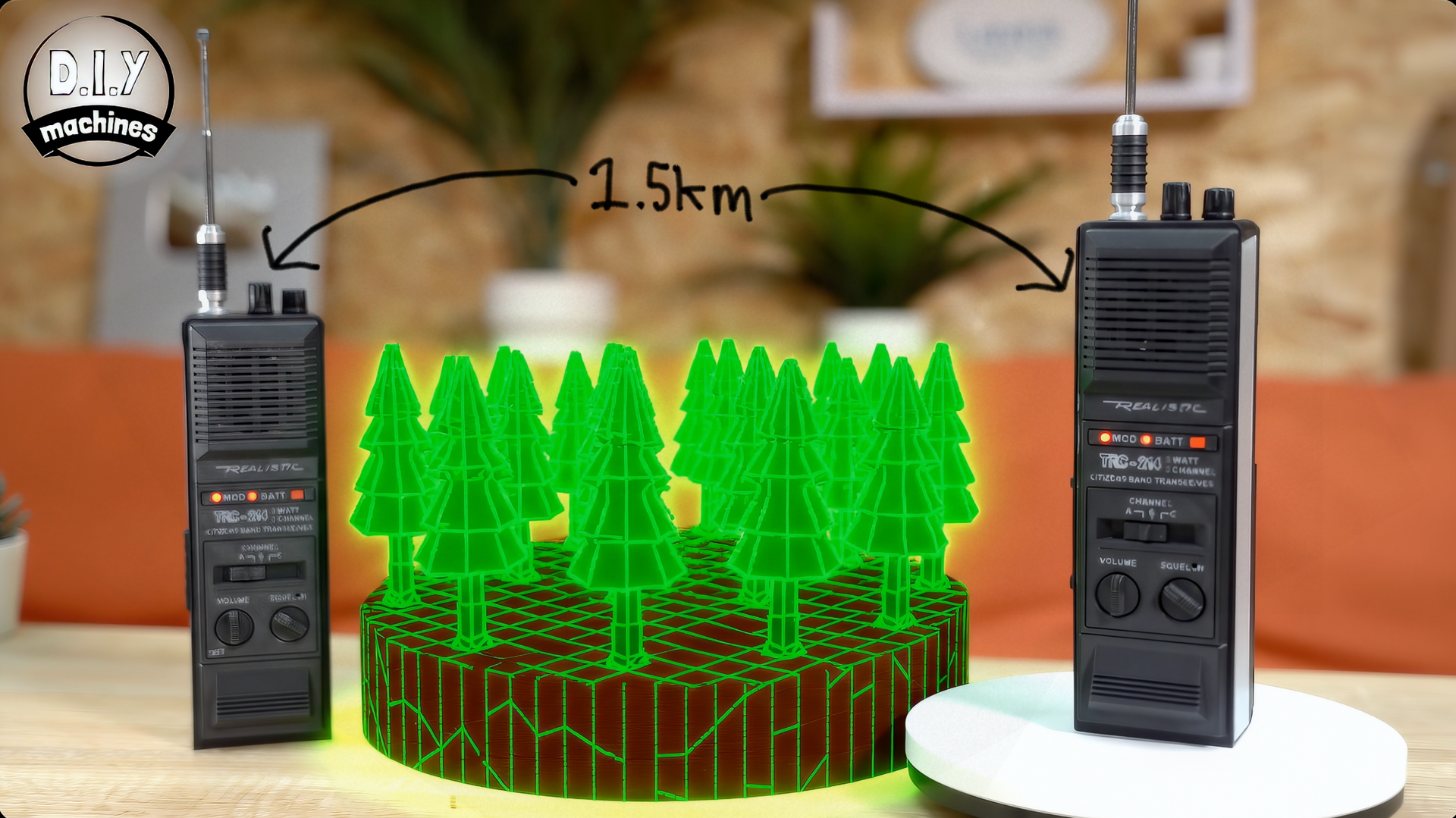
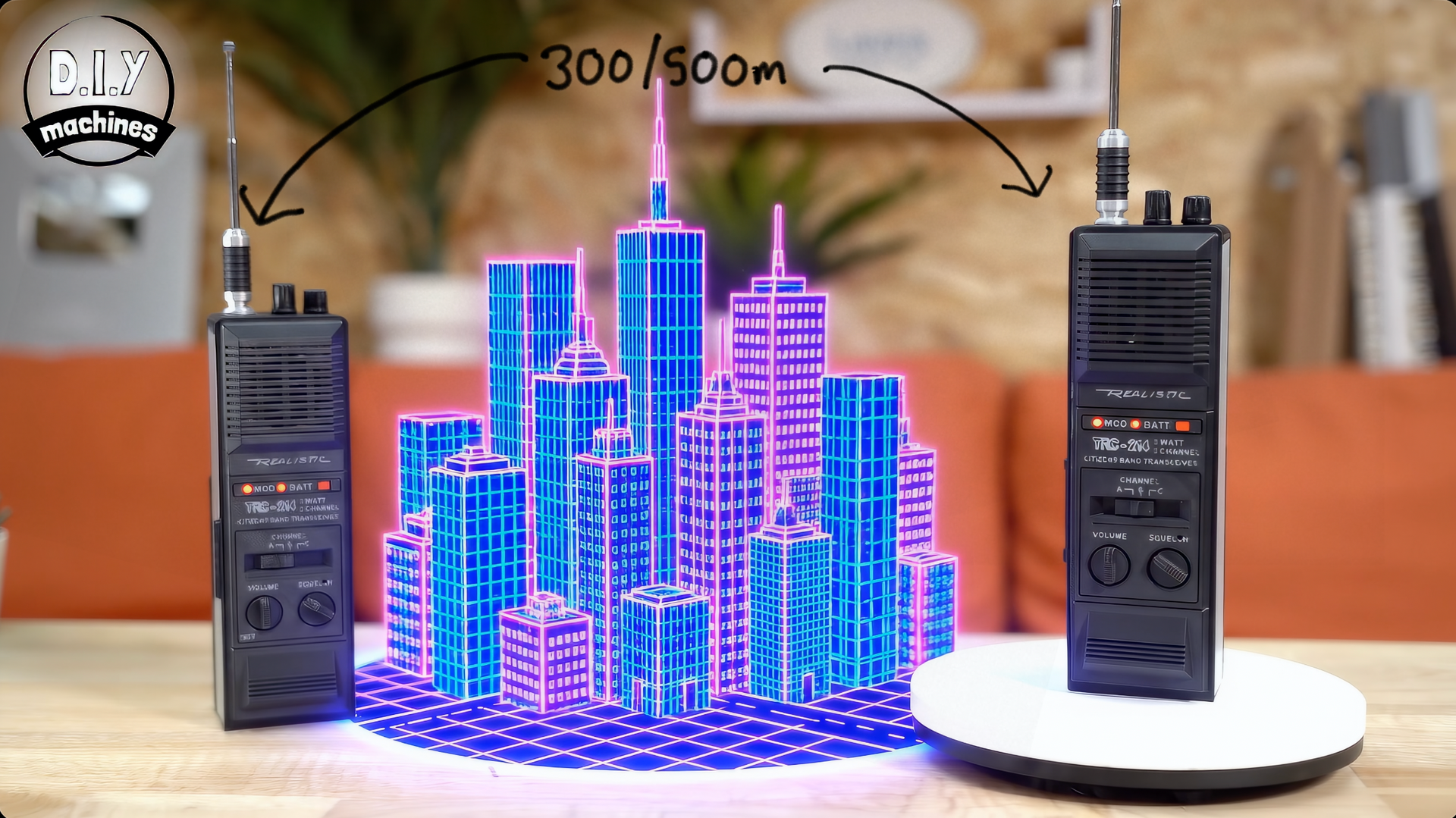
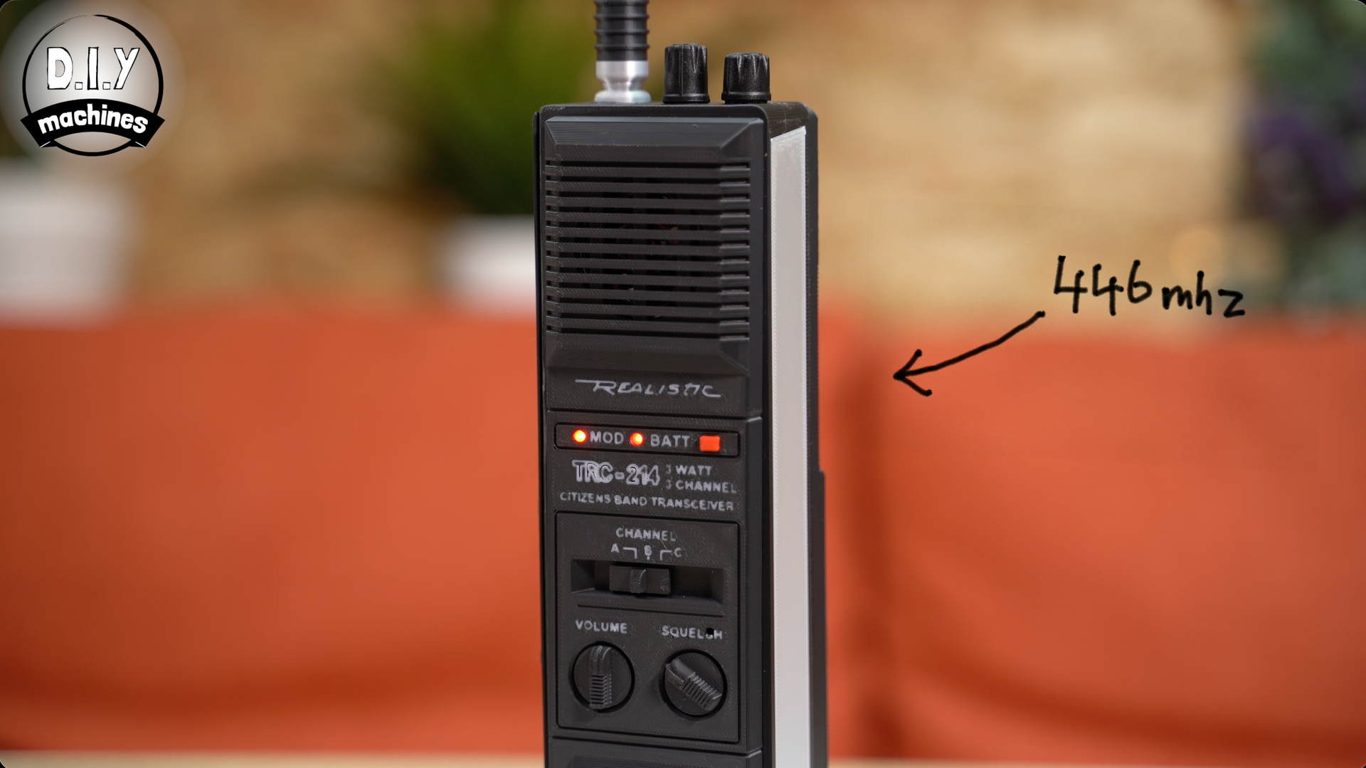
They use the 446mhz spectrum, and after testing them they have a range of about 1.5km in the open air and roughly 300 to 500m in built up locations. More then enough to be enjoyable. And of course, you can build more than just two and they’ll all work together plus there are 16 voice channels to select from.
I looked into building my own PCB and electronics circuit for this but the cost and complexity was rising - so at that point I decided to buy a low cost radio. A pair of these are just £19 on Amazon. I took them apart and then rebuilt them adding LED’s and other details to the build.
This means we also have a USB C rechargeable battery pack and, if you want, you can hook them up to your computer and program frequencies and codes using some free software.
As always I have created a high quality video build guide (see above) which also explains a little more about the project at the beginning of the video. It's an option to watch it as I have included everything you need in the written guide below - but it does sometime help if you become a little lost with the build process later on in this written guide and I put a lot of effort into it so it would almost be rude not to at least watch the intro. 🙂(Though I will of course try my best to ensure you don't get lost in these instructions! )

List of items used in this project and where to find them / BOM:
To build one of your own you will only need a few items for the relatively simple, but effective, project:
(As an Amazon Associate I earn from qualifying purchases.)
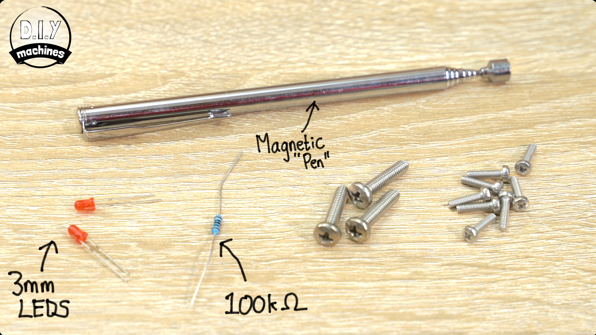
So, to build your own you’ll need:
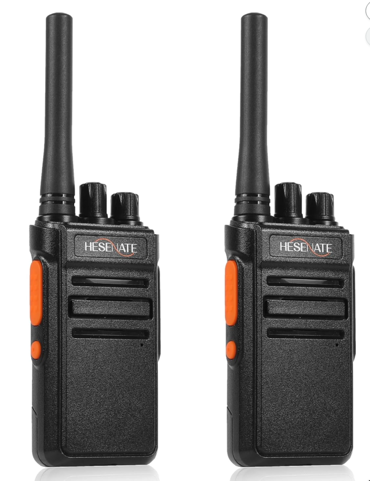
- Donor Radio (1 or more): I used HESENATE HT66 PMR446: https://geni.us/PMR446-Radio
- (Other radios might be usable, but the 3D CAD design would need updating. 3D files available on Printables: https://www.printables.com/model/1579255-build-working-stranger-things-walkie-talkies-how-t )
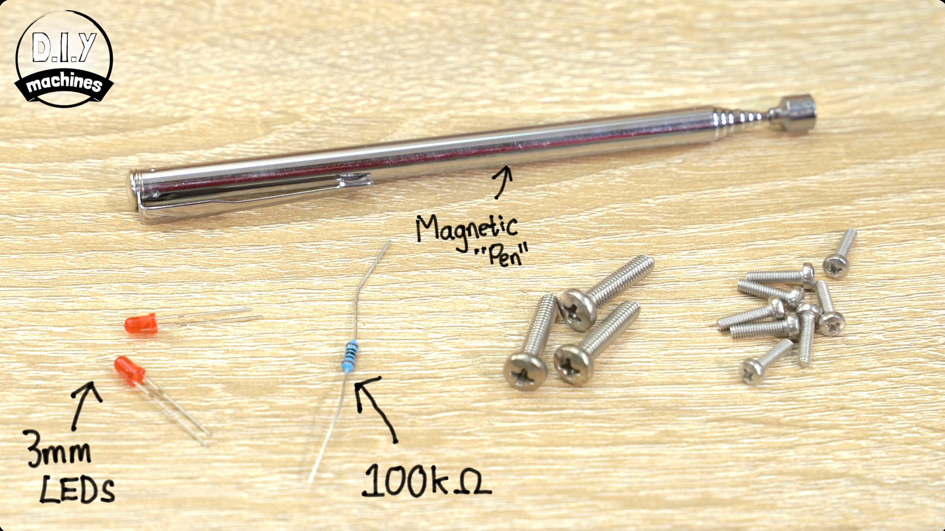
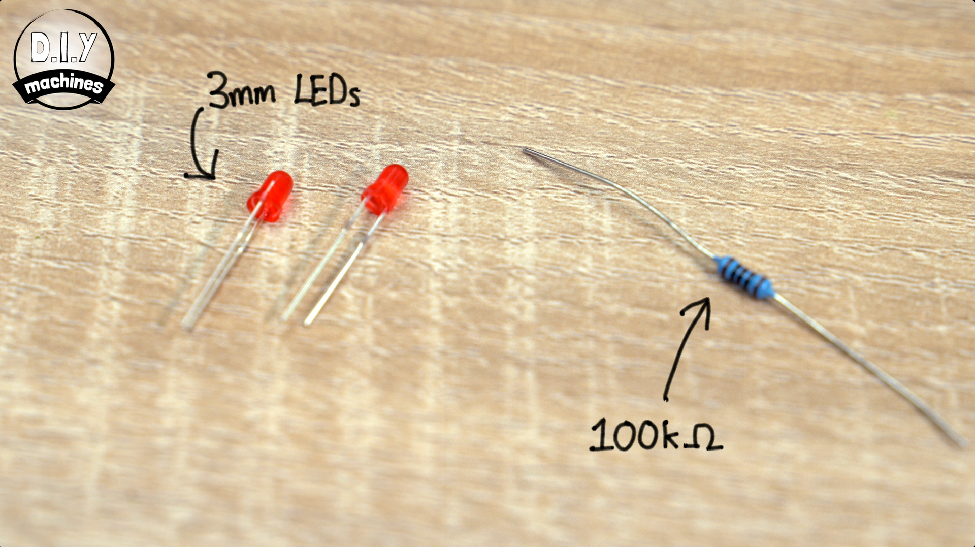
- 3mm Red LED’s (x2): https://geni.us/LEDs
- 100 Ω resistor (x1): https://geni.us/ResistorsKit
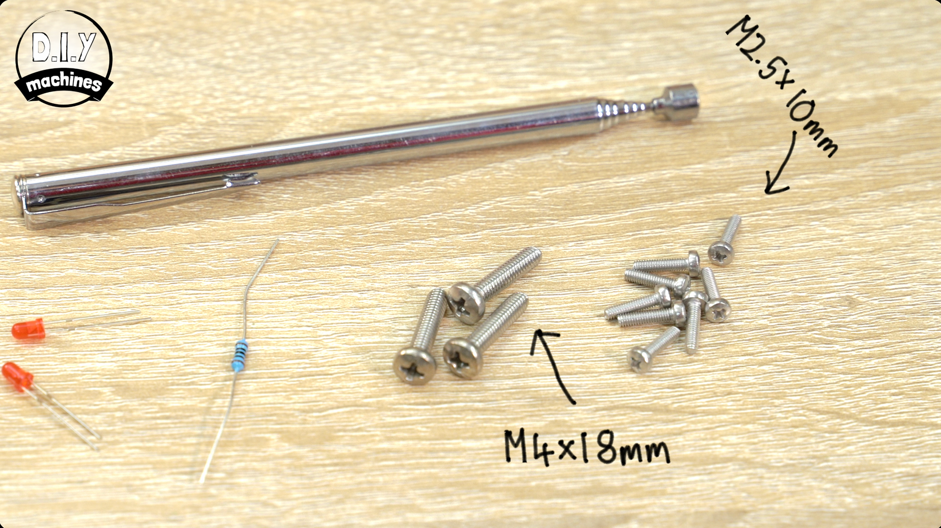
- M4x18mm Bolts (x4): https://geni.us/M4-Bolts
- M2.5x10mm Bolts (x8): https://geni.us/M2-5BoltKit
- Optional M4 Lock Nut (x1)
- Telescopic magnetic pen (x1): https://geni.us/MagneticPickUpTool
- 3D Printer Filament: https://www.3djake.uk
- Some 20AWG wire (around 0.8128mm in diameter): https://geni.us/20AWG
It’ll also be ideal if you had some heat shrink tubing, or insulation tape to protect our circuit later.
Downloads:
Please 'like' the model on Printables. It really helps me out. Thank you.
3D models for printing: https://www.printables.com/model/1579255-build-working-stranger-things-walkie-talkies-how-t
International shipping Etsy shop: www.diymachines.etsy.com
How to Build your Stranger Things Style Walkie-Talkie
Step 1: Disassembling the radio
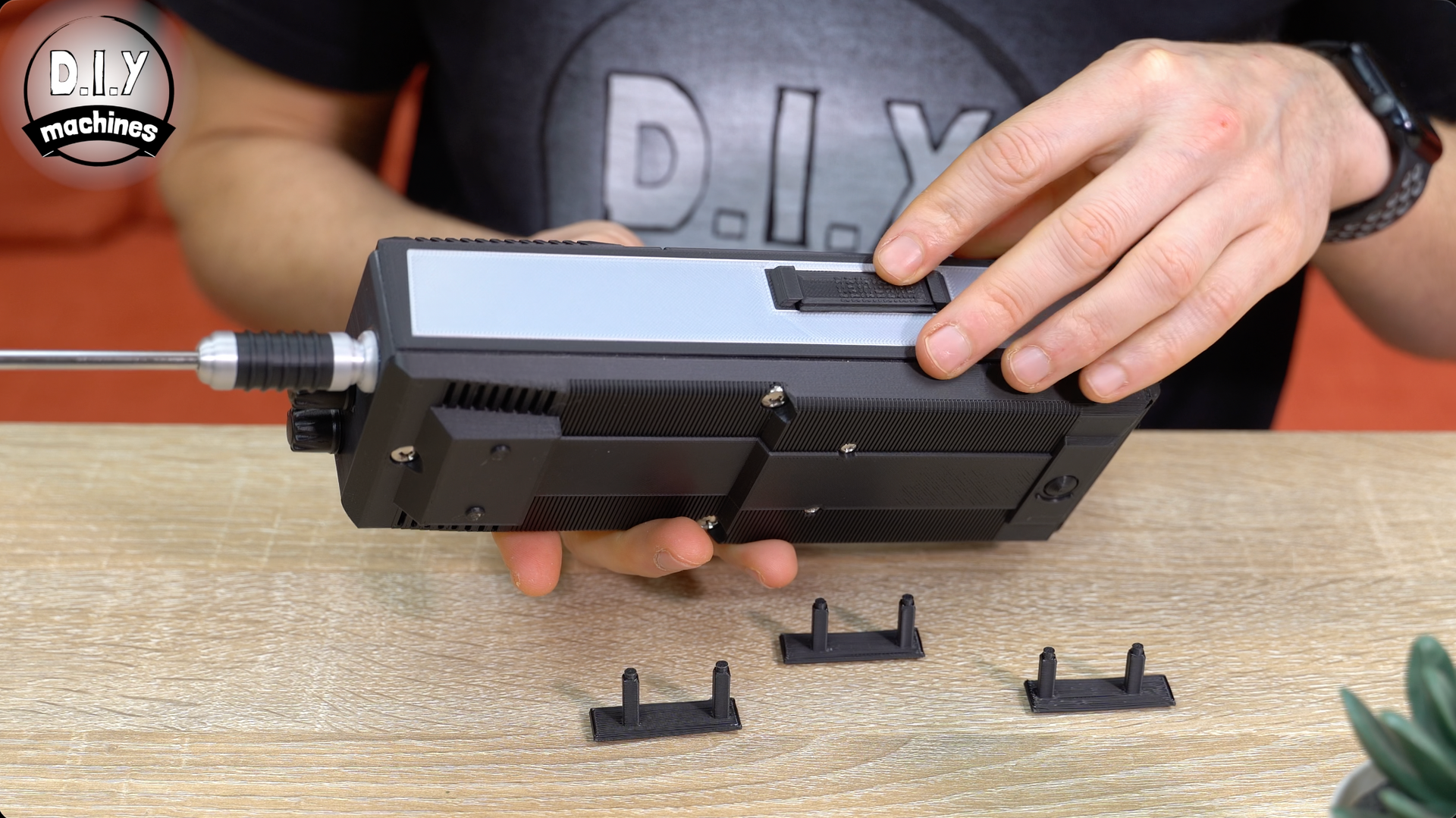
First we remove battery by opening pulling on the little clip at the base of the radio and then sliding it down and out.
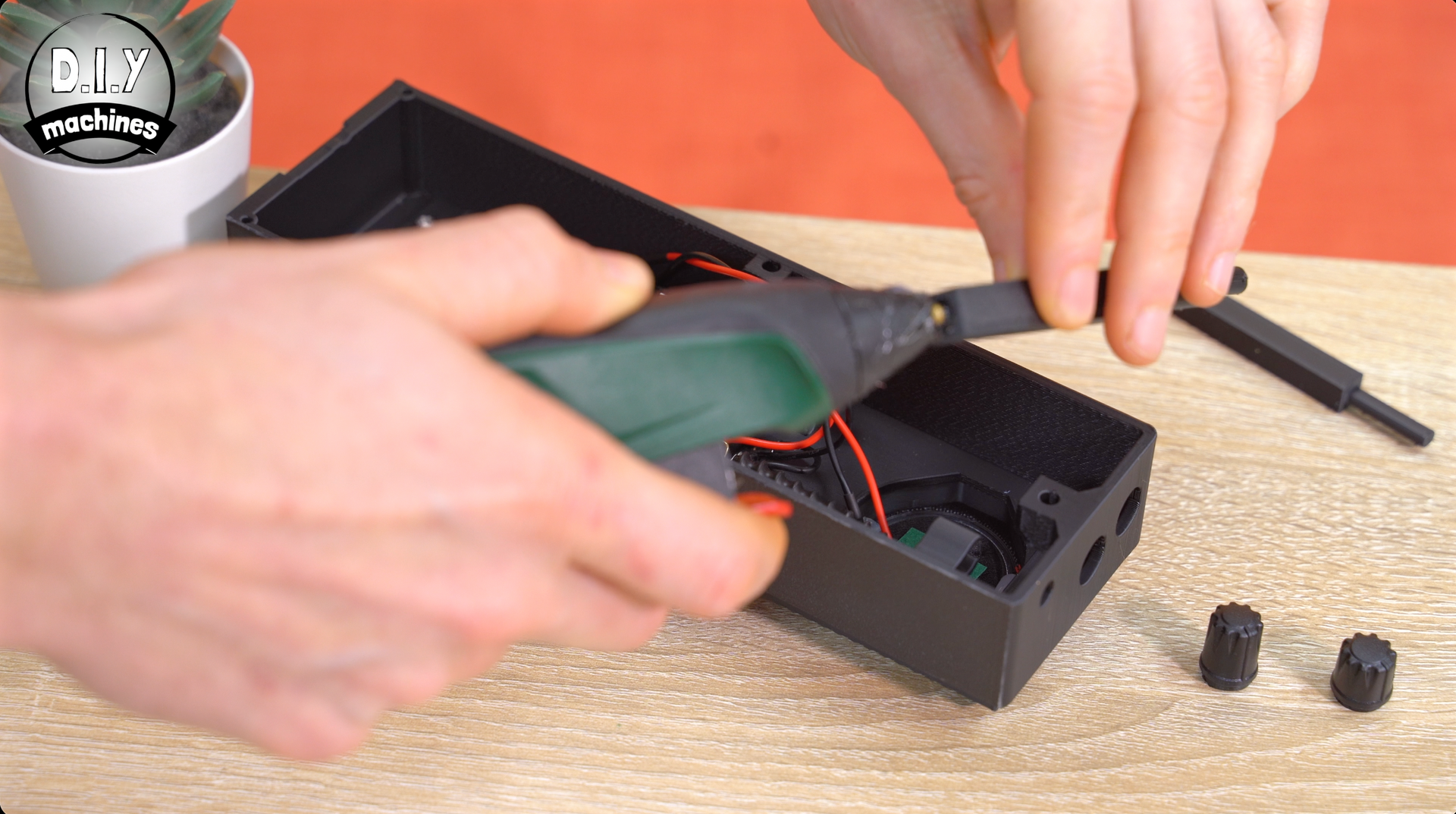
Next, using some pliers to help your grip, pull off the two dials at the top. They're on pretty tight but will just pull straight off.
Underneath these dials are some circular nuts which we can use a flathead screwdriver to turn anti clockwise to un-tighten and remove.
After this we can pry off the silver back piece. Lift from bottom, alternating sides to loosen it by the tabs, and then carefully pull up and partially back out the bottom as we need to cut the two speaker wires roughly in the middle before fully removing the silver back. You may find the antenna need's gentle persuasion out of the antenna sleeve it's currently residing in - this is fine but be careful not to damage it.
To remove the speaker, start by removing any glue around it’s edge and then carefully pry it up at the sides.
Finally, unscrew (and save the two screws) from the electronics board to separate it from the silver chassis.
With this done we can move onto some 3D printing and create the first part, the middle of the Radio Body in the next step.
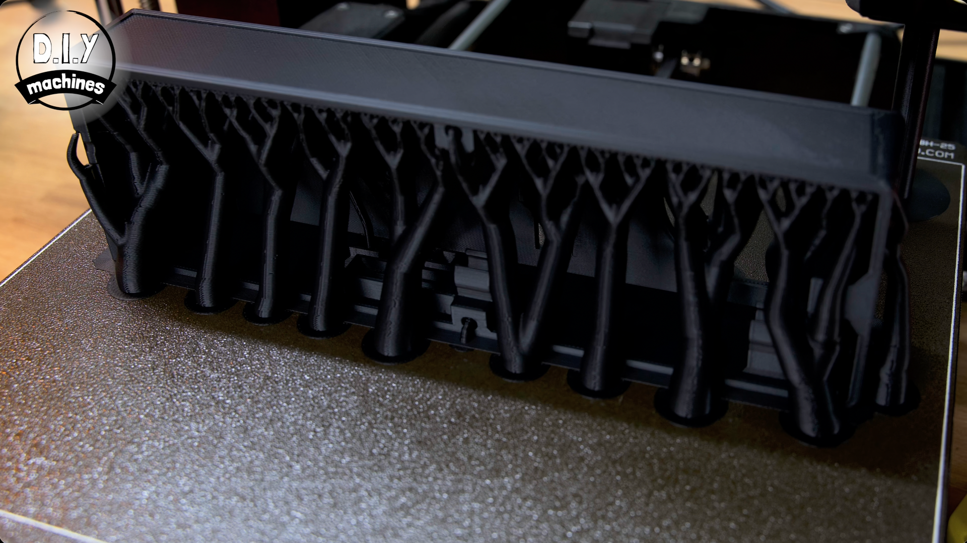
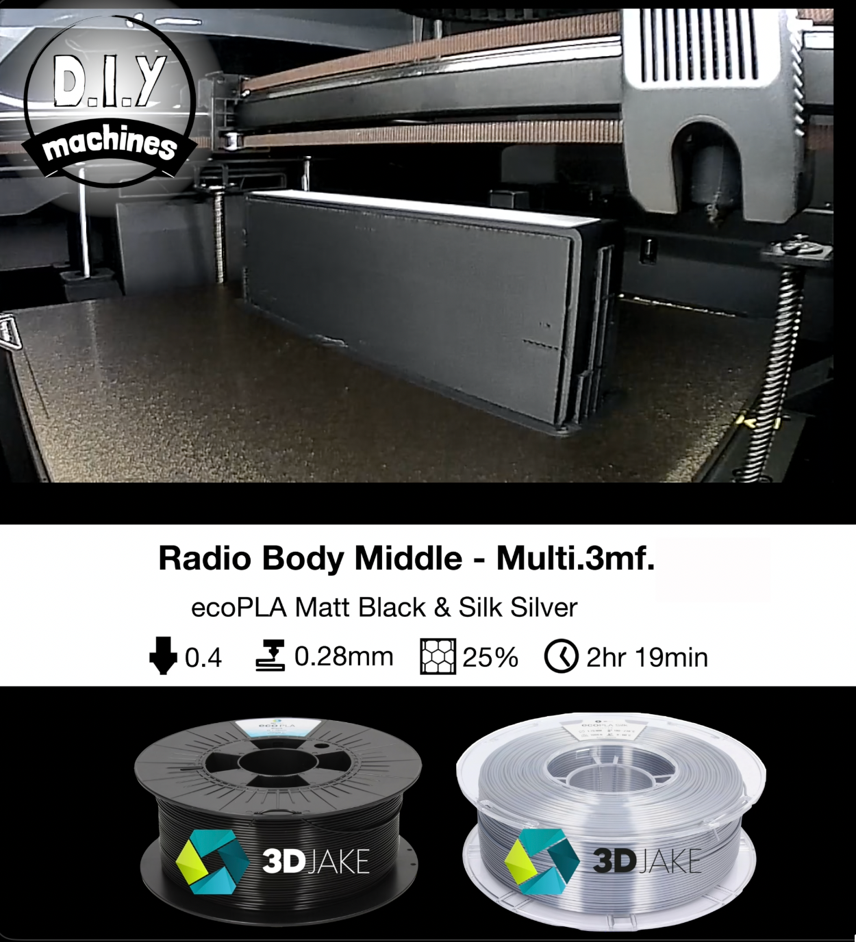
Step 2: 3D Printing the Radio Bodies Middle
As we go through the step of 3D printing and assembling this project I have included and will describe methods for both people with a multi-material/colour printer and for those who have a more traditional single nozzle/extruder printer.
For these parts U used a Silver Silk PLA and a Matt Black PLA.
If you’re using a multi-material printer go ahead and print the file
‘Radio Body Middle - Multi-material’ and if you’re using a single colour printer you’ll need to print
‘Radio Body Middle - Single’ and
‘Silver Inserts Both Sides’.
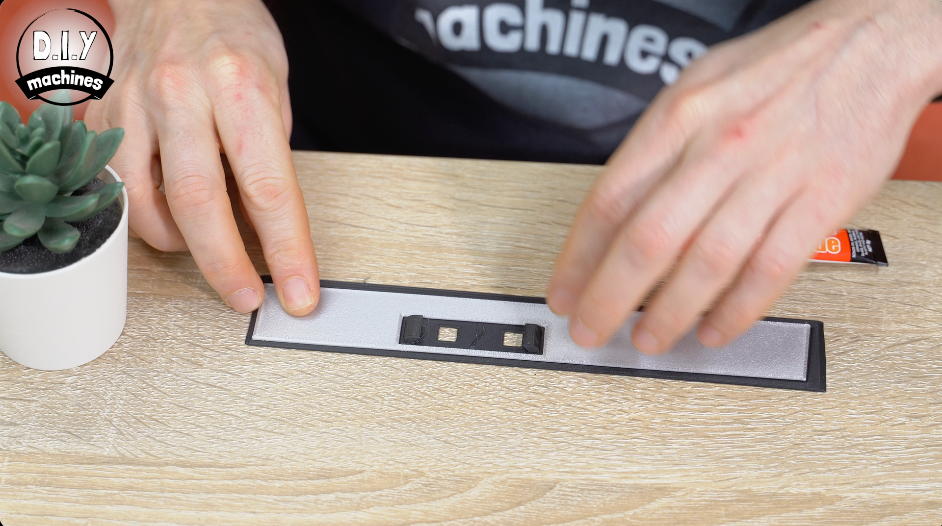
Then those of us with the single filament printers can go ahead and glue the solid silver piece into the recess at the top of the print saving the other print for a later step. The multi material one is already assembled. :)

Step 3: 3D Printing the Radio Bodies Front
We can also print (and shortly begin installing components into) the front of the radio. Multi material printers you’ll want ‘Radio Body Front - Multi’ and single nozzles it’s ‘Radio Body Front - Single’
The multi material comes with markings already included ion the front, for the single colour print I found this trick from the Youtube channel FuzzyLogic which can work. Here is a link to his video, and I will also briefly describe it below: https://youtu.be/W2f5lI1R6dg?si=K8IdM1HdP4LCR7YX&t=42
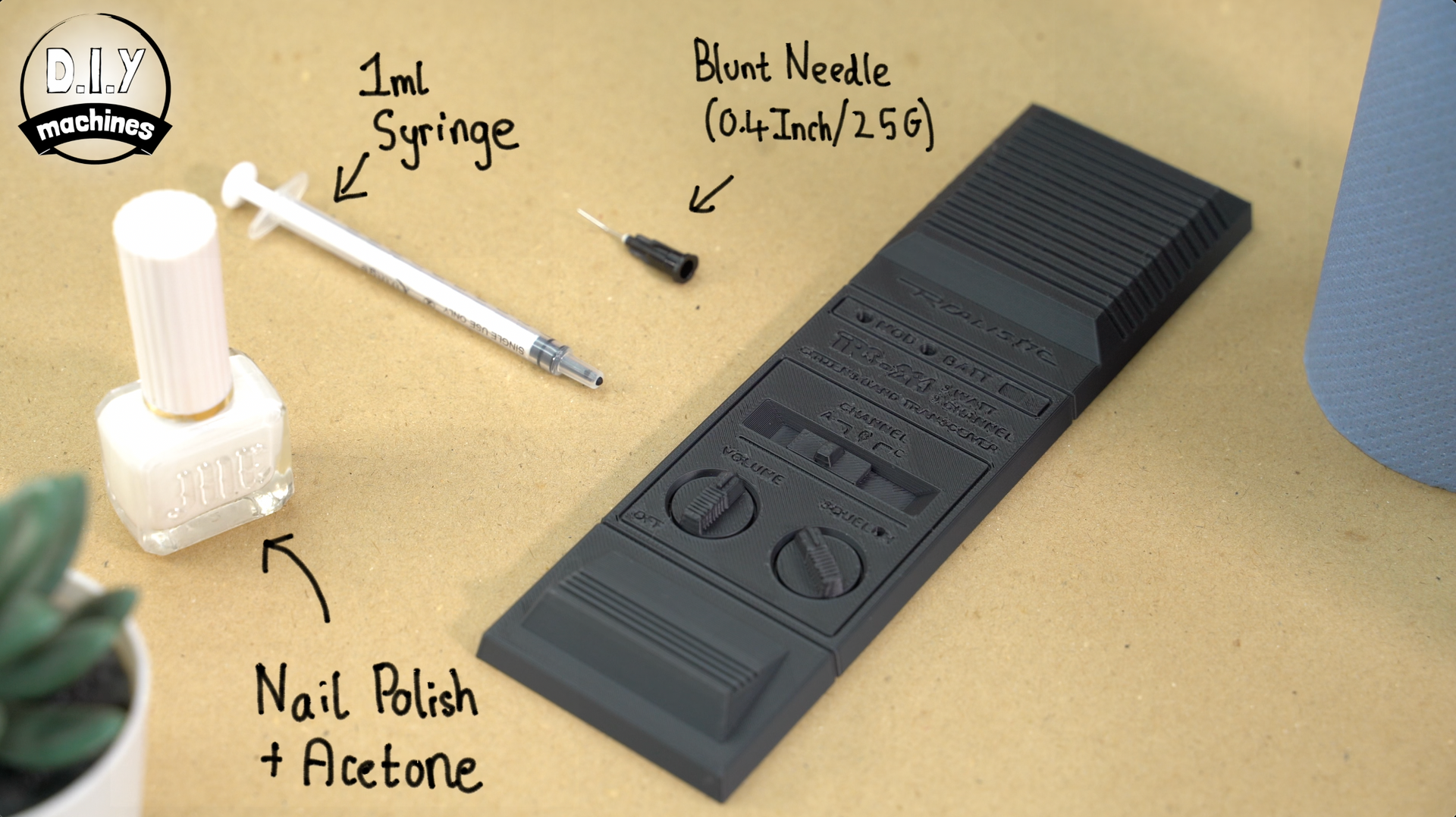
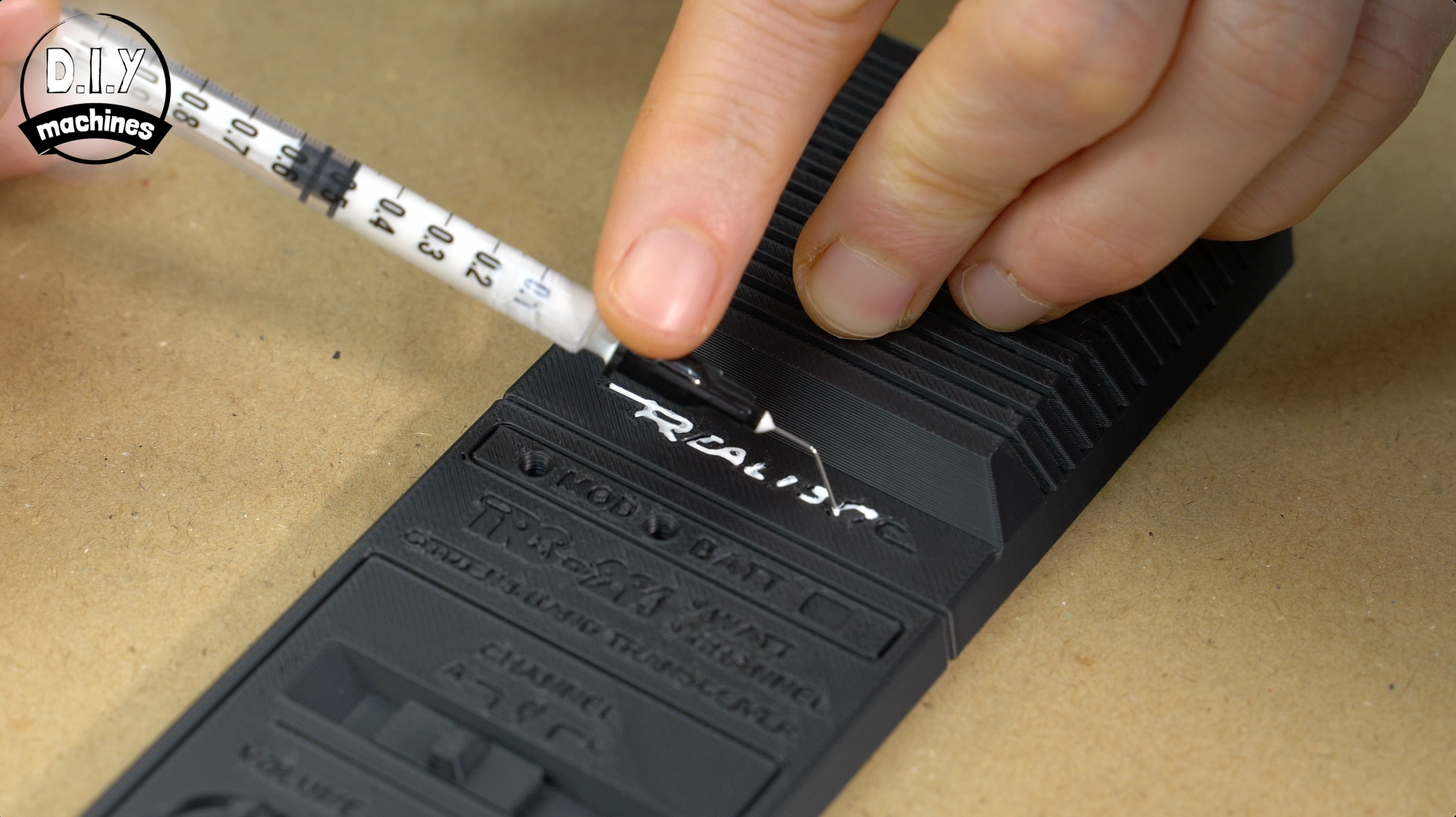
You essentially thin nail polish with acetone and then use a 1ml syringe and blunt tip needle to add the polish into the inlays. You’ll need a steady hand and can wipe any excess. Fortunately, my somewhat questionable skill at this matches the fact the radio should look old and a little worn by its years.
Step 4: Adding the LED's
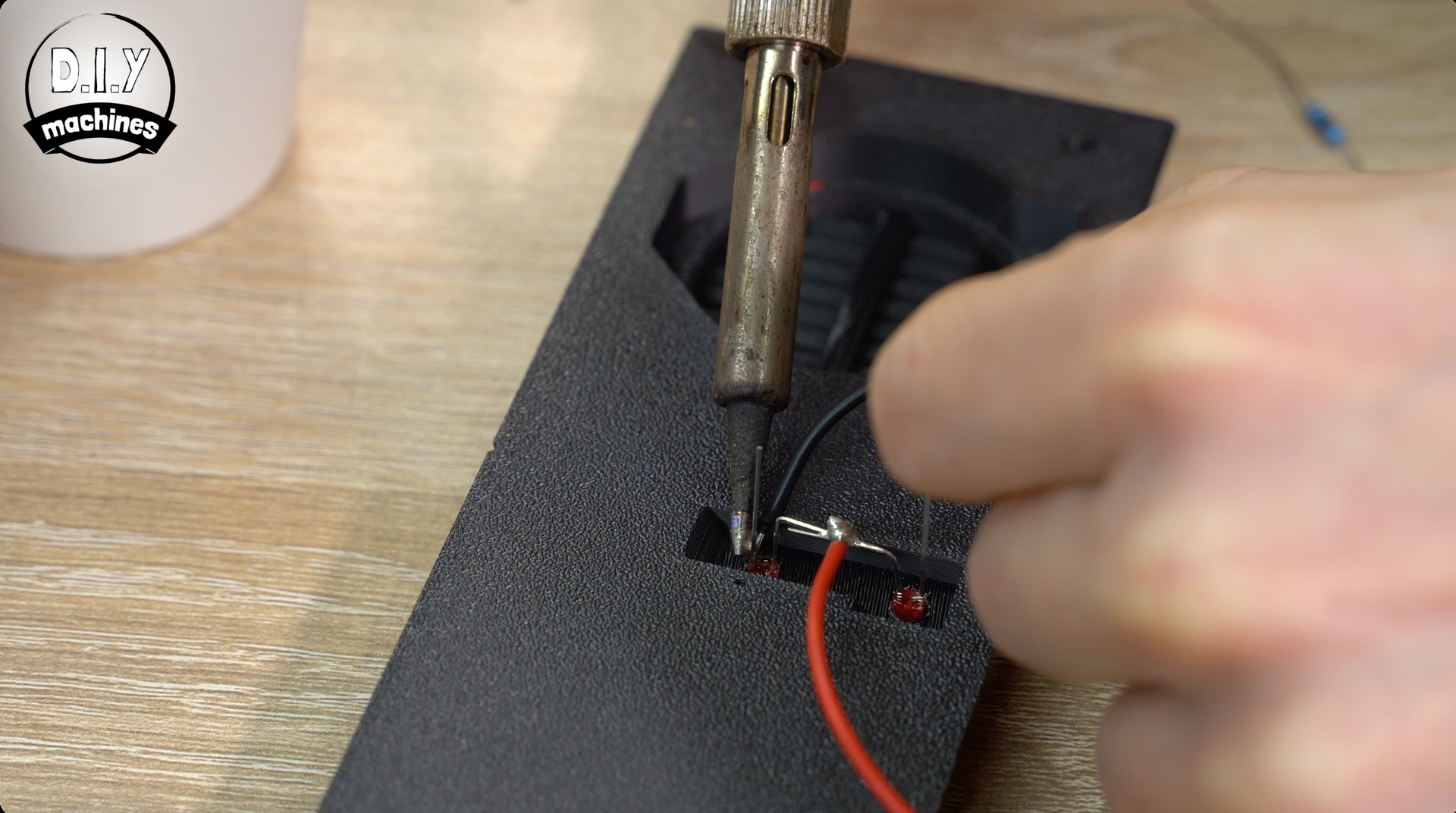
We’ll fit the LED’s first. They need to be wired in parallel through a 100 Ω resistor. Before we go through that it's important you understand the polarity of LEDs.
The LED’s have a longer leg on it’s positive side also known as anode. For general knowledge the shorter leg and side with a flat notch is the Cathode or negative side.
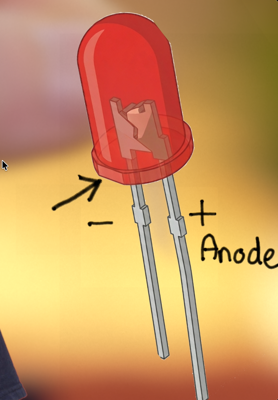
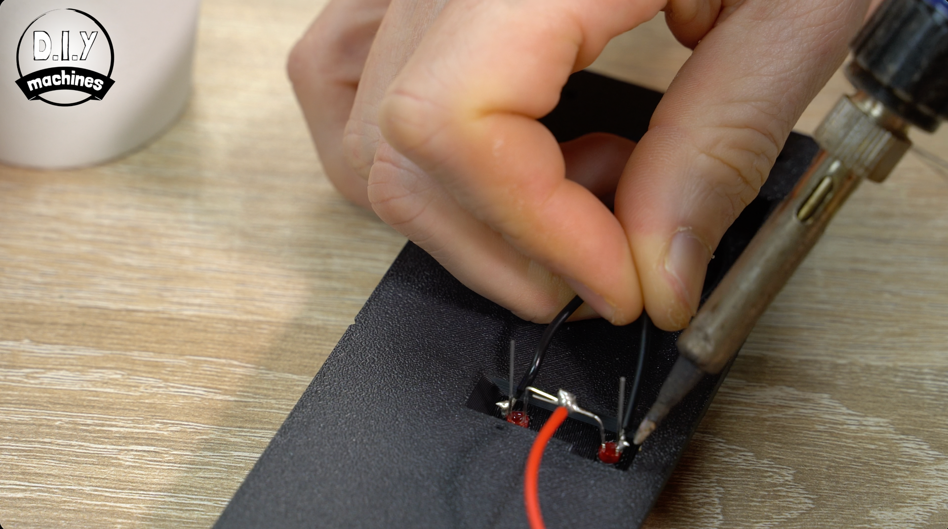
Push fit the two LEDs into their cut-outs from the reverse side so that the two positive legs are towards the middle. We can then bend them together and solder them in place.
To this we will solder a 15cm length of wire. (I'd recommend using a red wire if you have some).
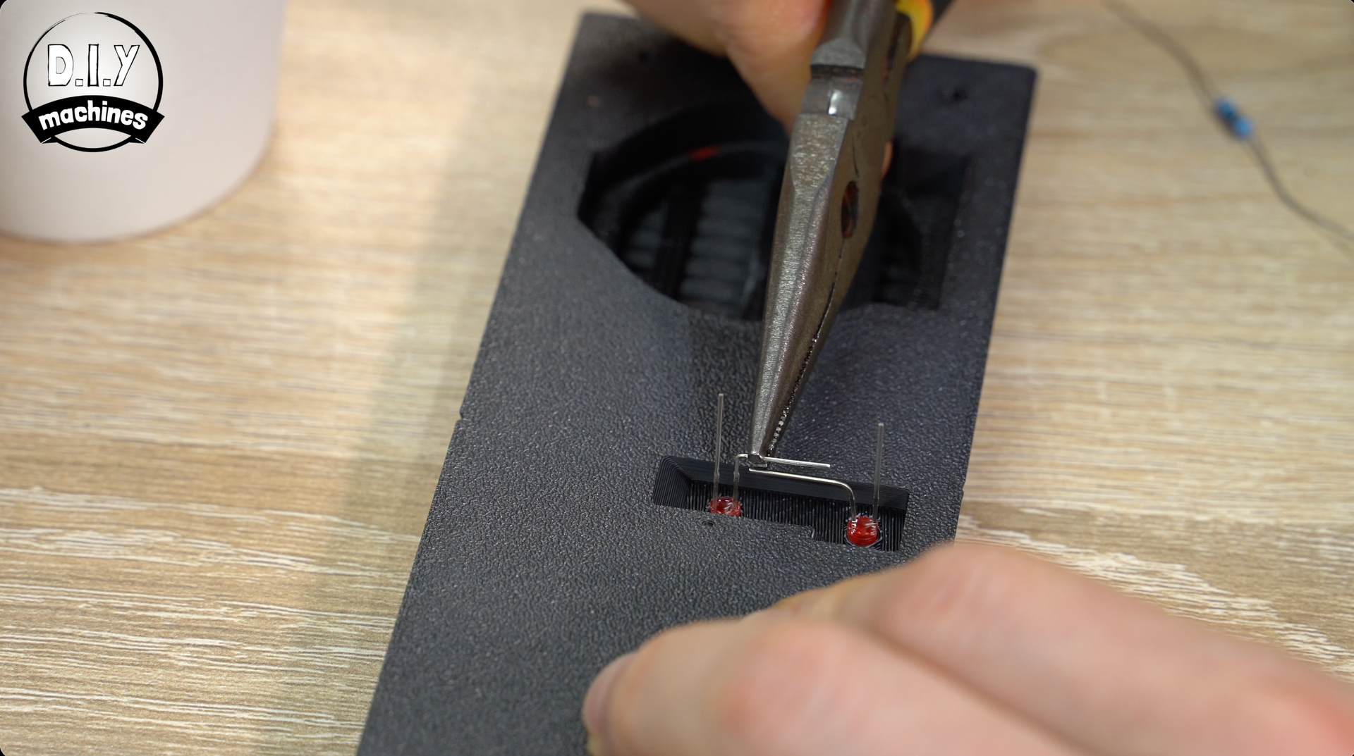
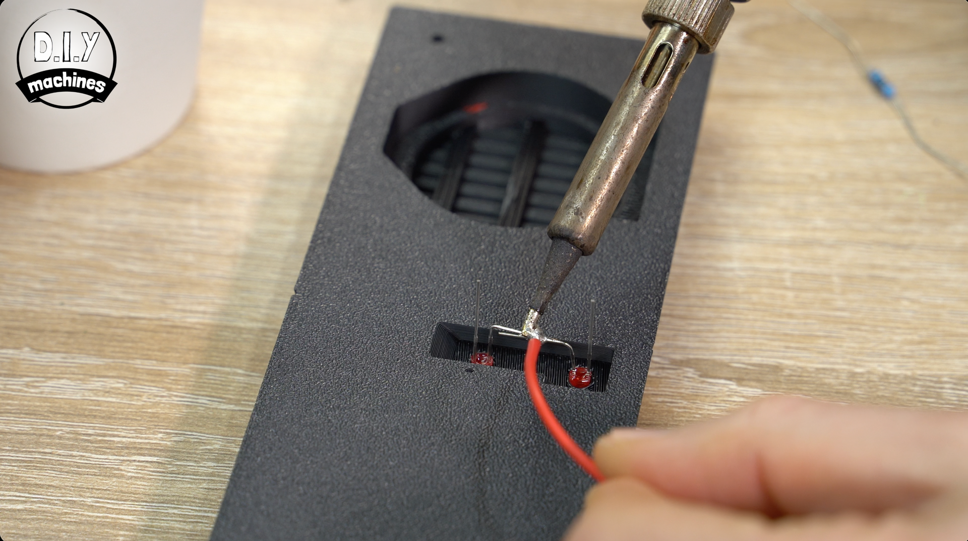
For the negative cathode side of the LED’s use a short length of wire to join them together close to their bases, and then another 15cm longer length to connect one of the cathodes. (Black this time if possible).
Pop some heat shrink on the wire but don't shrink it, this is just us getting ready for connecting in a short moment.
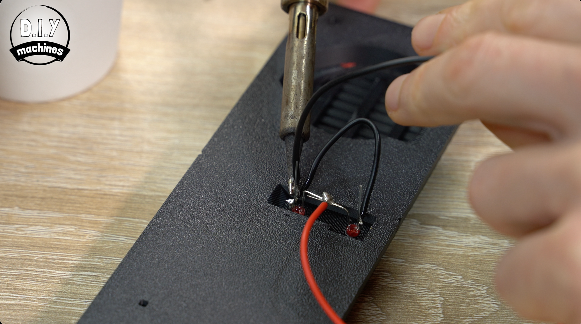
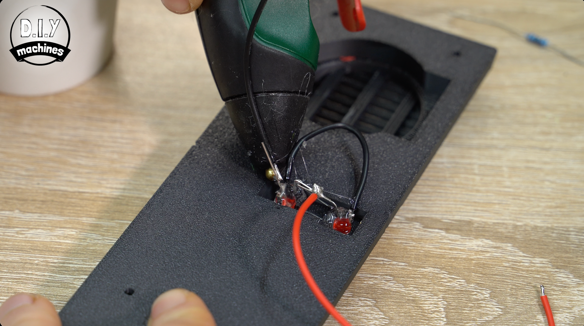
Use some hot melt glue to secure the LEDs into place and to help prevent any of the wires from short circuiting later on.
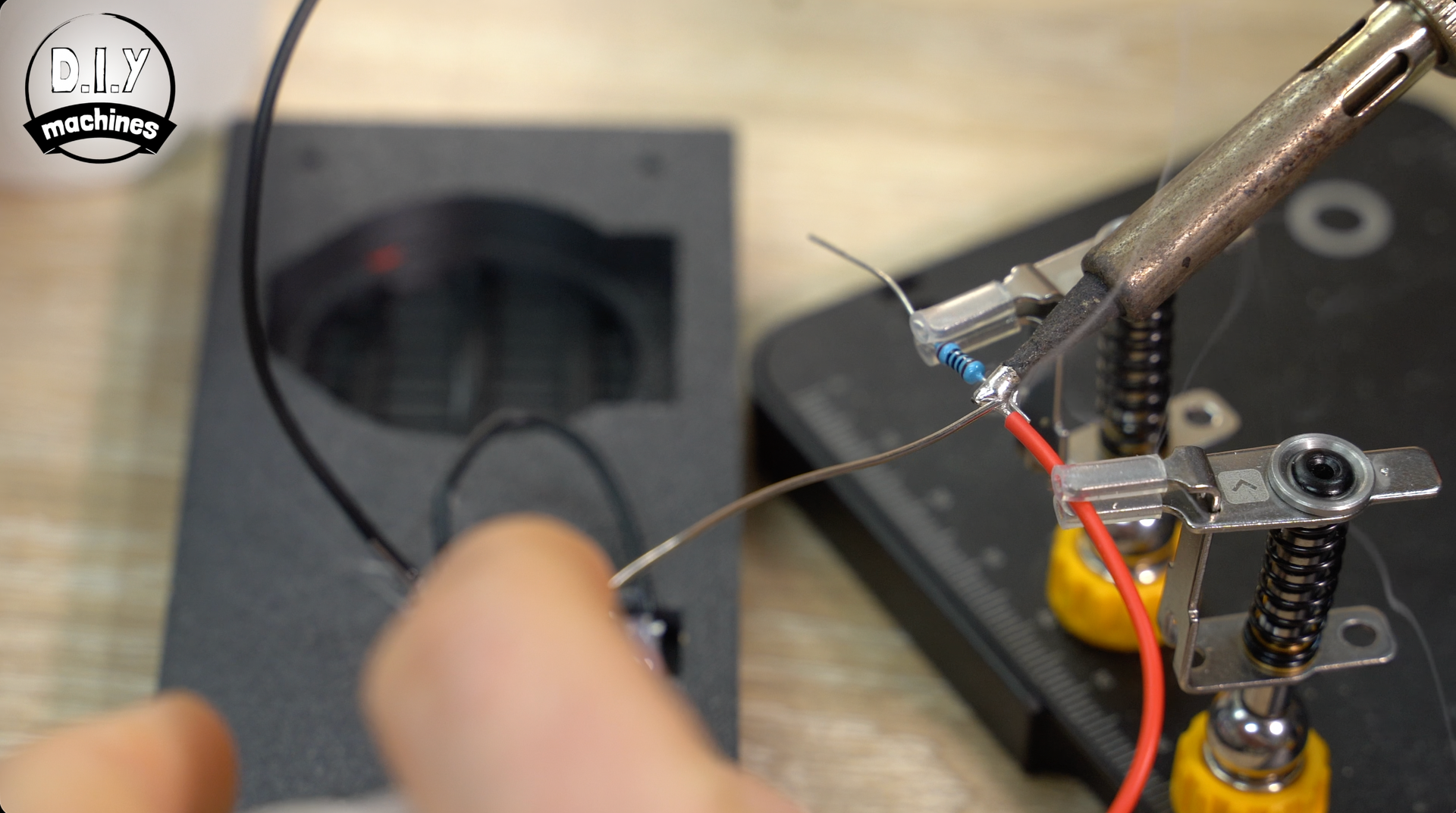
We will then add our resistor to the end of the positive wire coming from the LED's. Pop another short length of heat shrink over this end for later if you have it, if not insulation tape can used instead later.
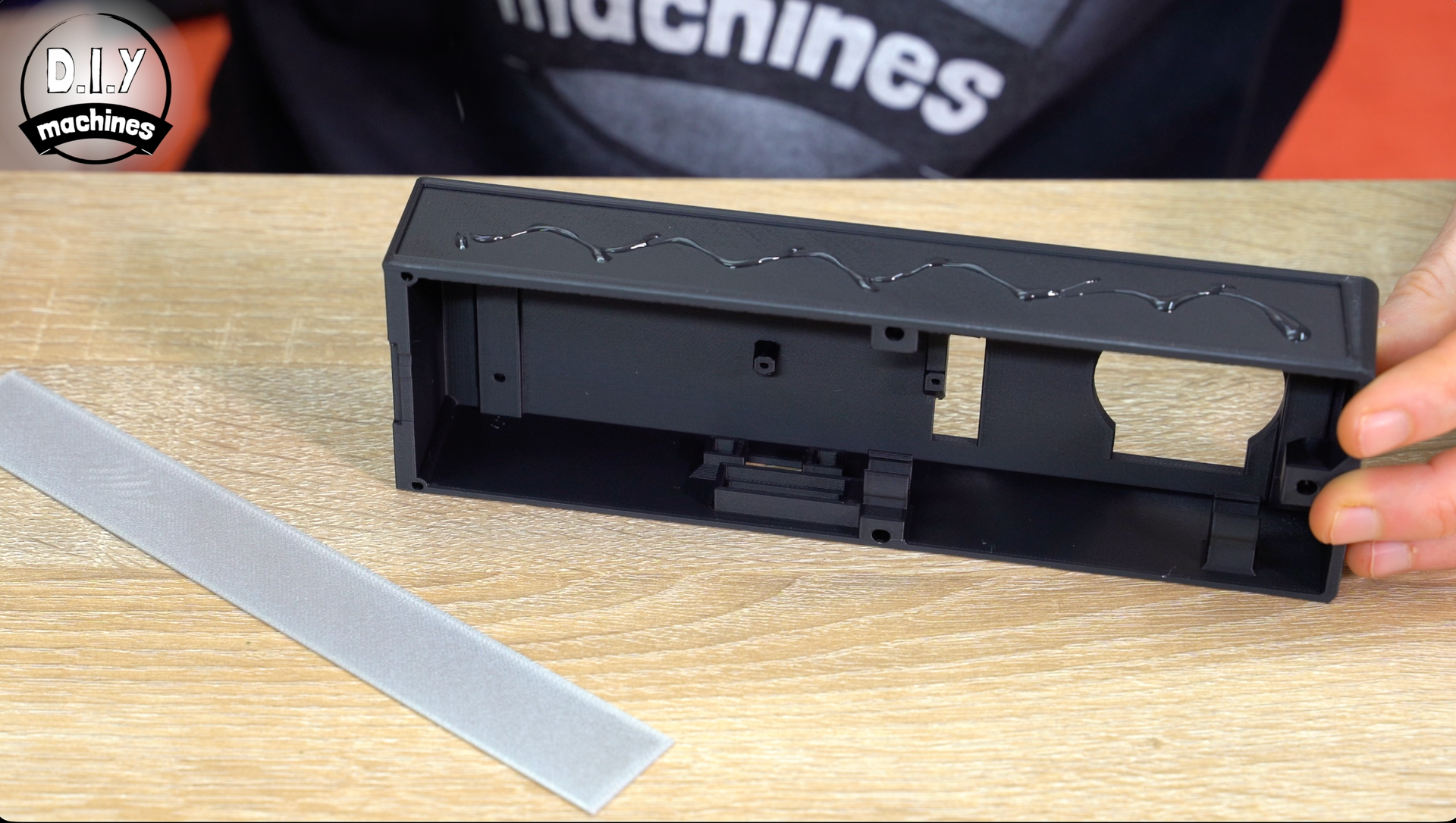
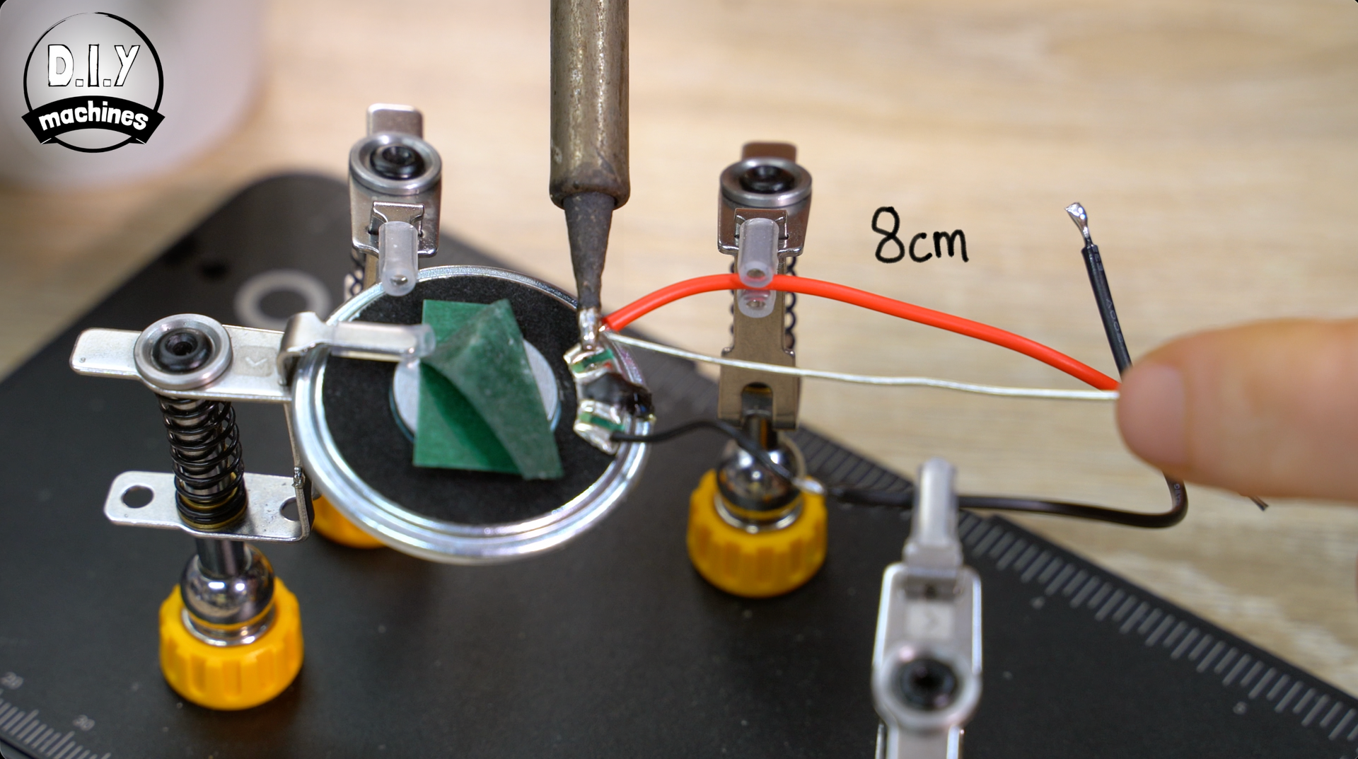
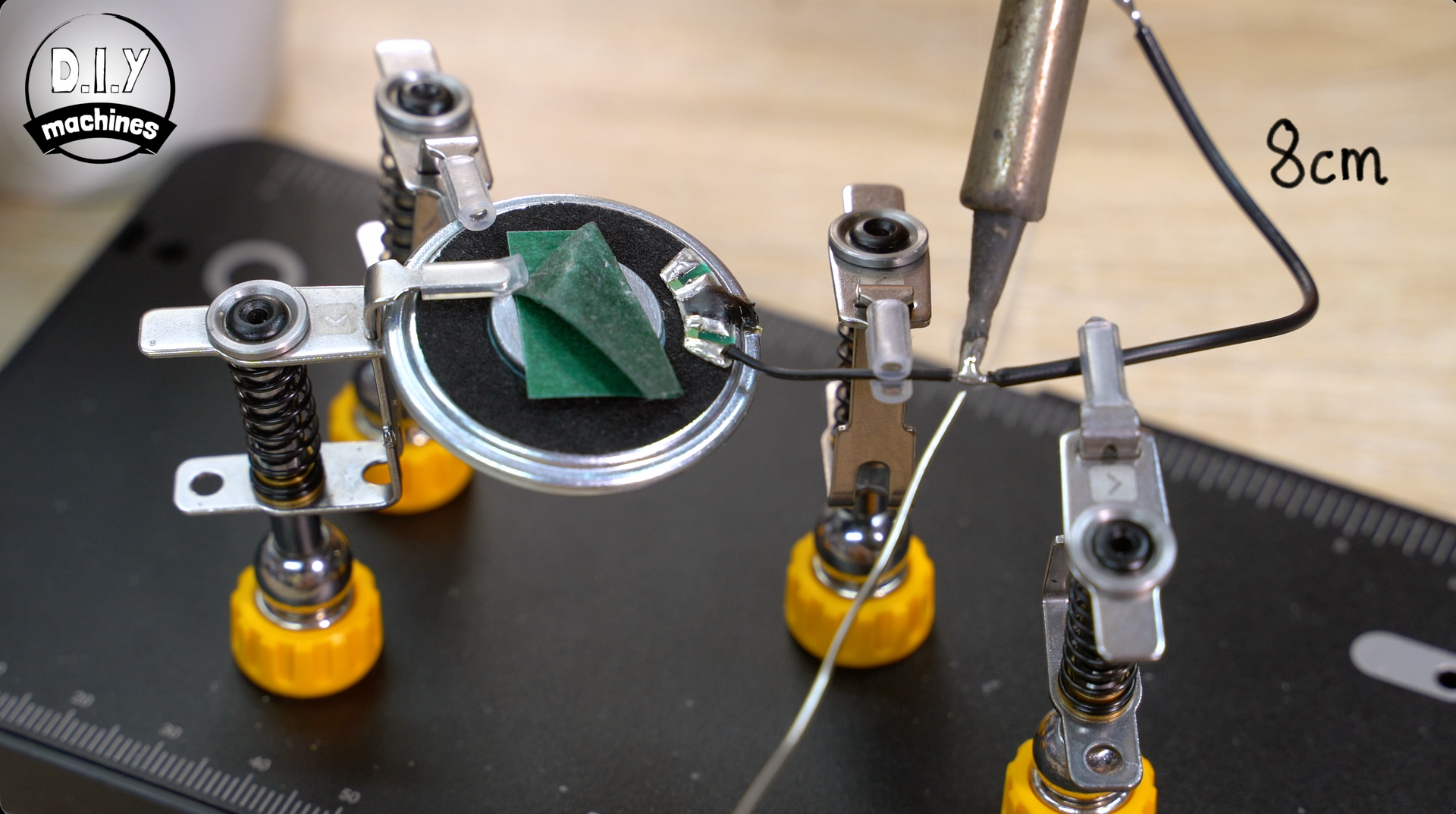
Step 5: Preparing the Speaker
To get the speaker ready we need to extend the two wires on the speaker module by about 8cms. If you accidentally broke an original speaker wire off during disassembly that’s ok (I did by accident) - just attach your new 8cm long wire directly to the speaker itself.
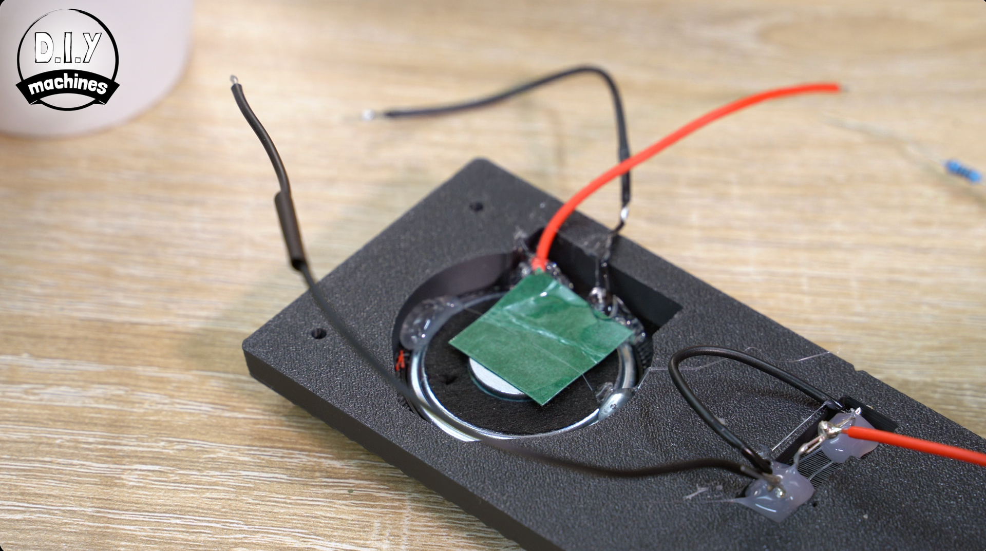
To fit the speaker in place, pop it into it's recess in the 3D printed part and then use a small amount of glue to help hold it in position and act as strain relief on our cables.
Step 6: Attaching The Two Prints
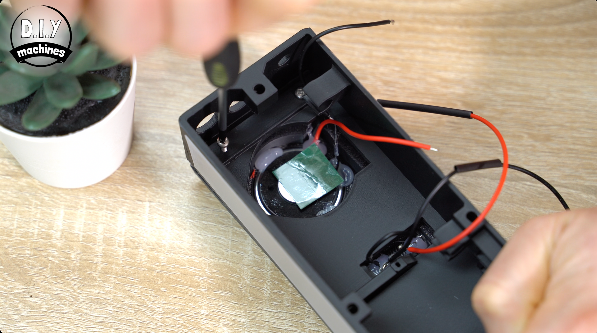
To attach our first two 3D printed sub-assemblies you’ll need to pass the speaker and LED wires through the cut outs. Then we can combine the front panel to the printed middle section of the radio.
Use four m2.5x10 bolts to attach the printed parts - the bolts go into the four corners on the inside of the prints.
Step 7: Connecting The Electronics - LEDs
With this in place we can take our circuit board and begin attaching the LEDs and speaker components from earlier.
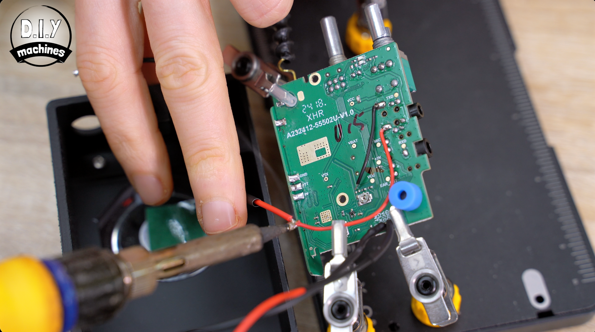
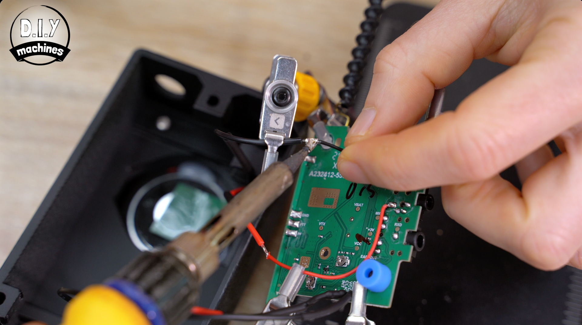
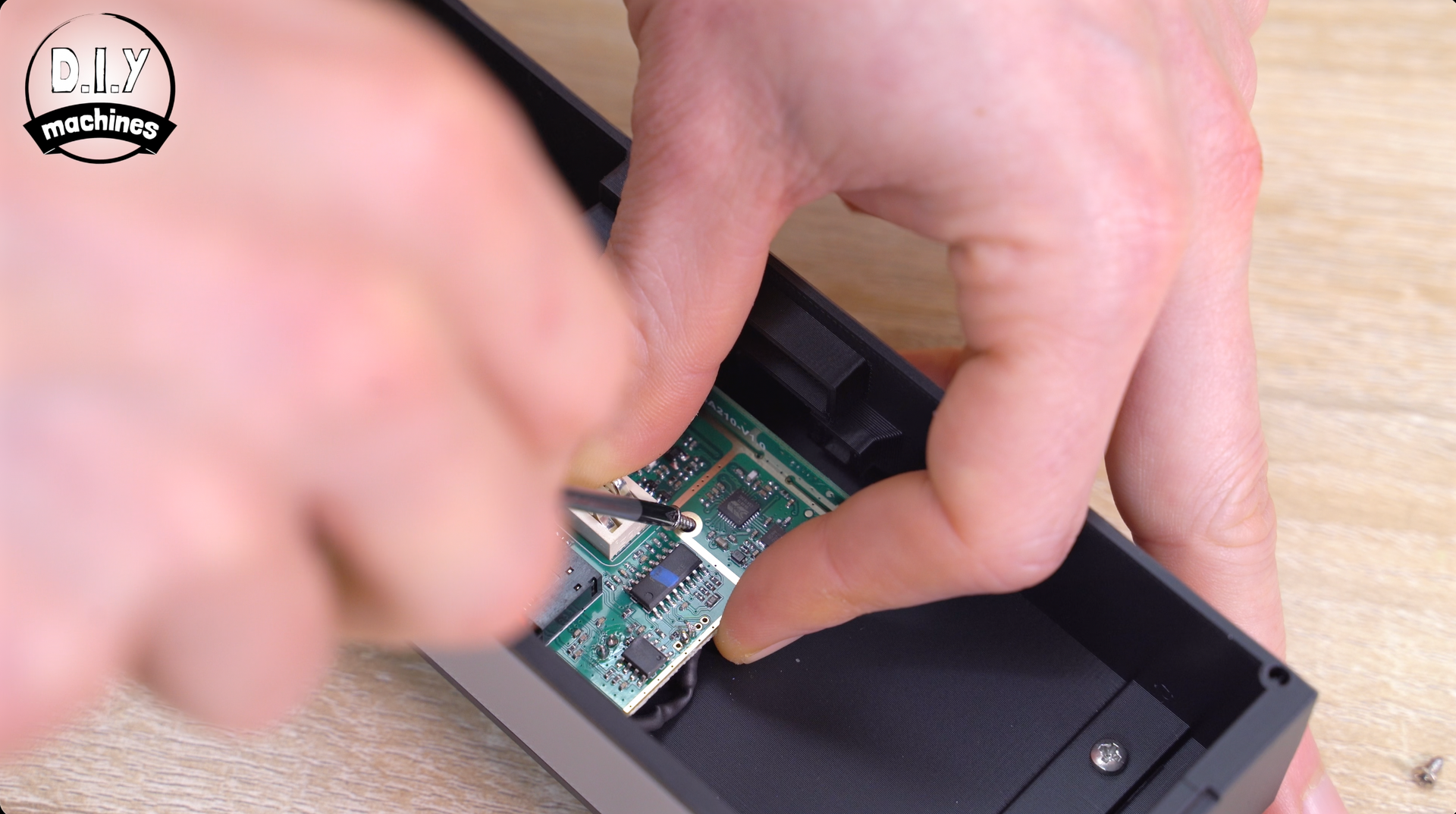
First take the other end of the resistor attached to our LED’s positive (anode) connection and solder it to the pin marked VCC on the radio circuitboard. This will provide us with a regulated 3v when the radio is switched on.
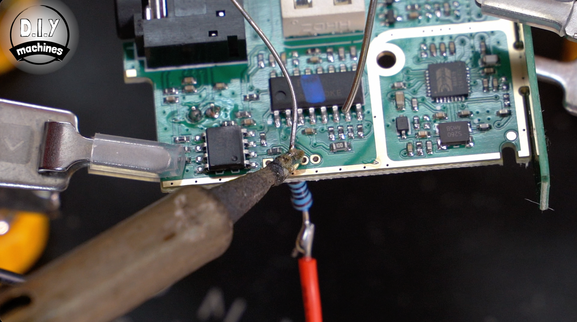
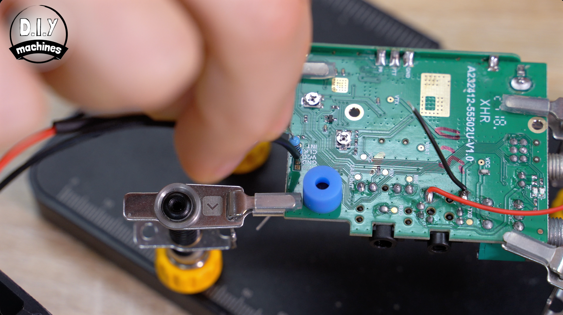
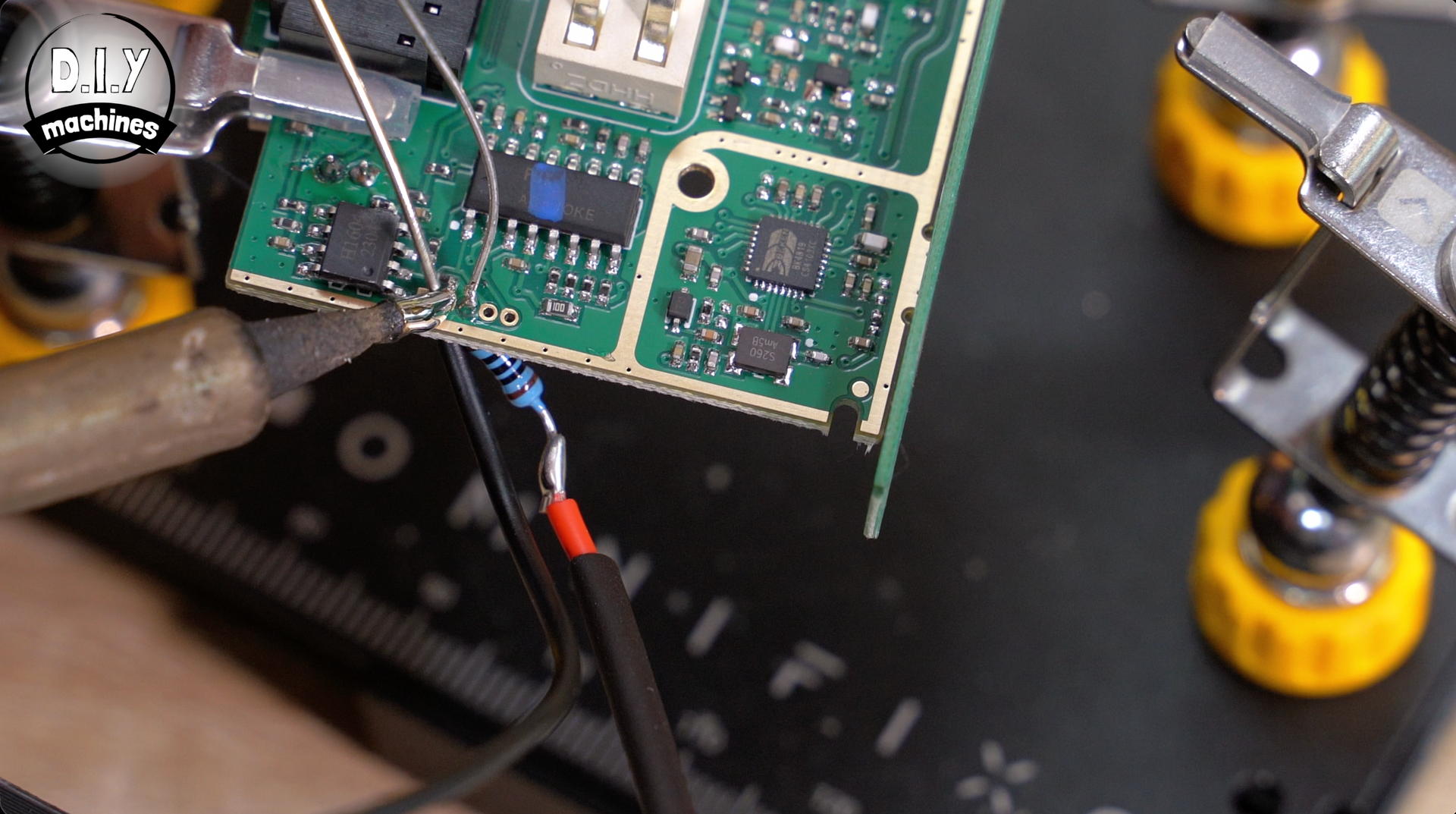
The wire coming from the negative Cathodes is attached to the GND pin on the circuit board being very careful not to bridge the gap between the pads.
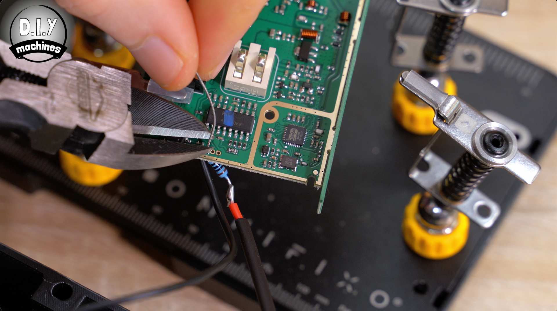
We can then insulate this wither either the heat shrink prepared earlier or some insulation tape. We can also trim of any excess from the underside of the board.
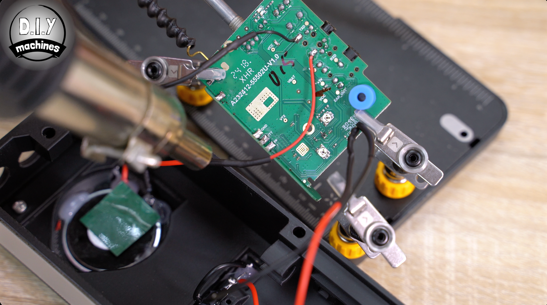
Step 8: Connecting The Electronics - Speaker
This is paragraph text. Click it or hit the Manage Text button to change the font, color, size, format, and more. To set up site-wide paragraph and title styles, go to Site Theme.
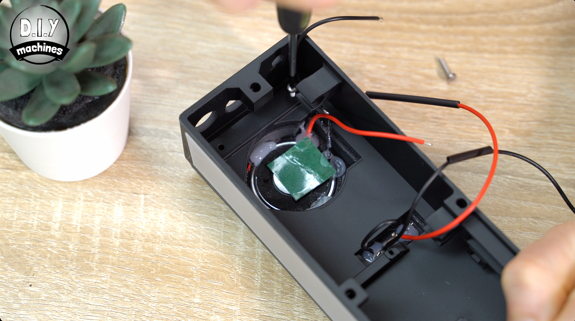
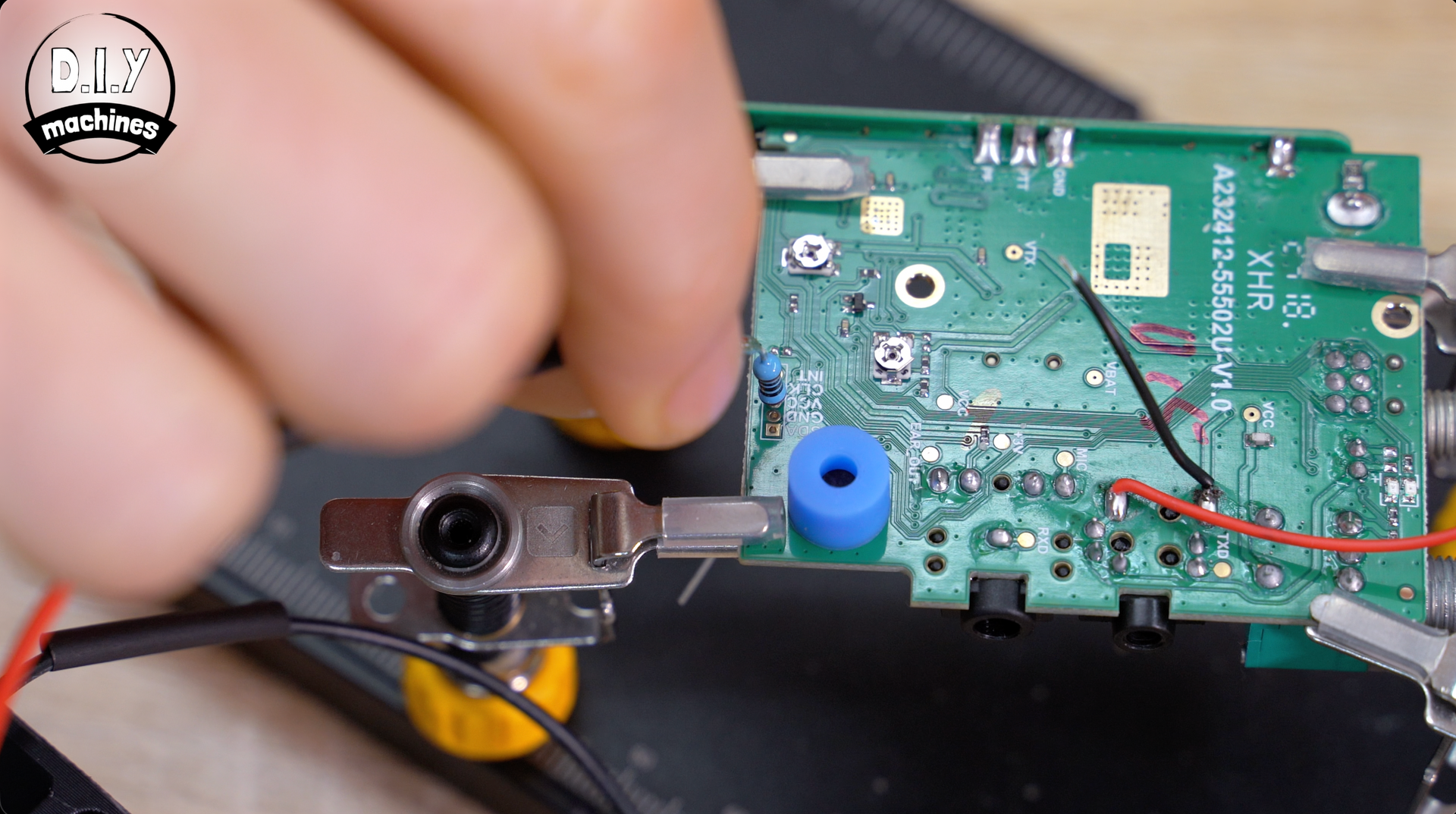
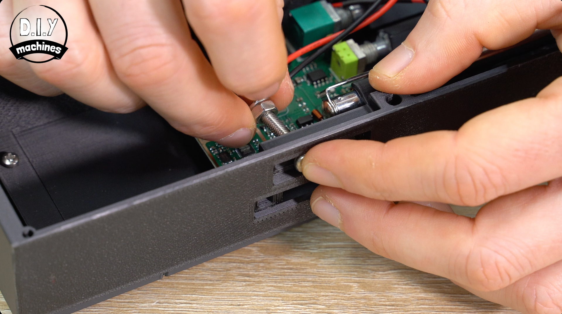
Step 9: Securing the PCB
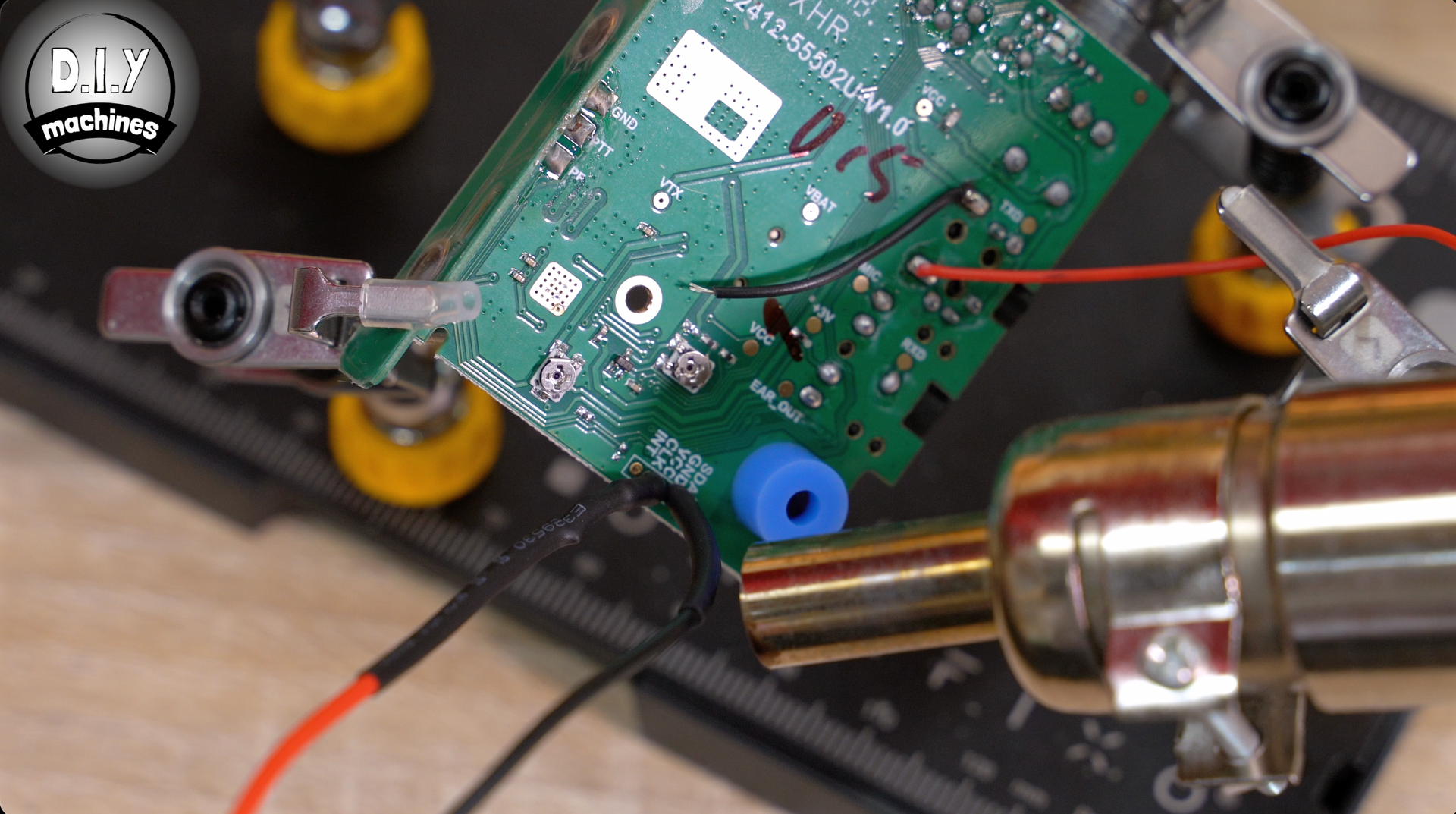
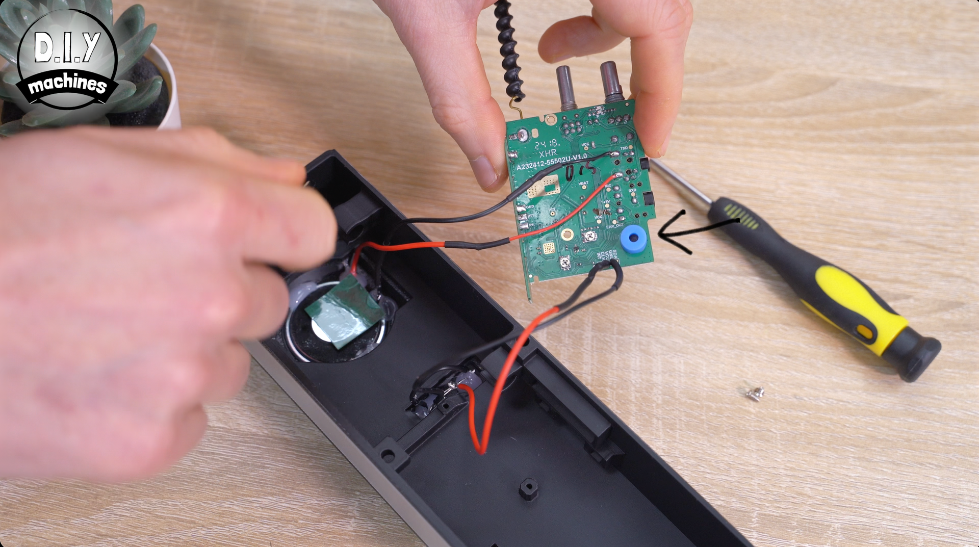
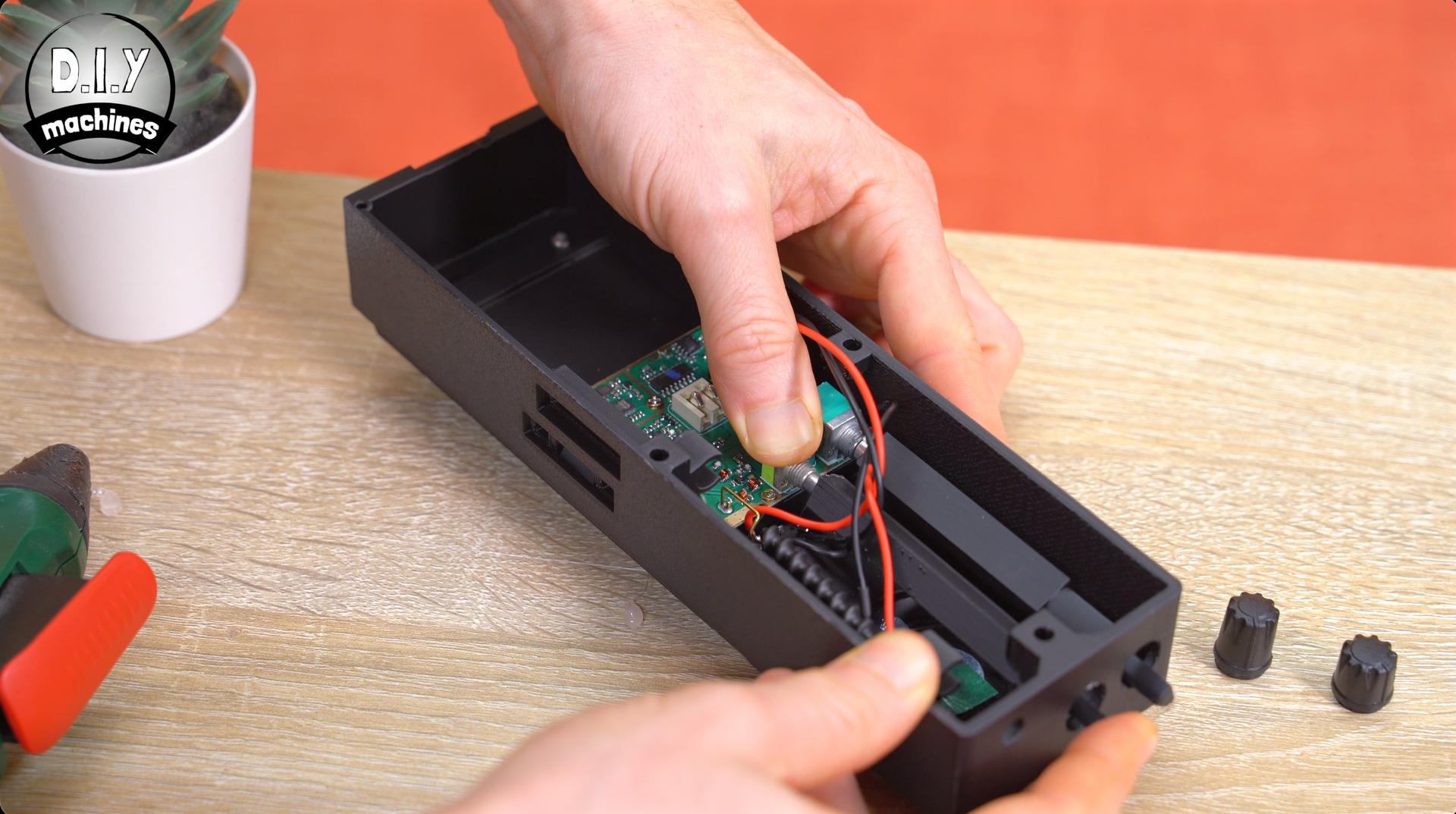
Before we install the circuit board, check that the blue silicone sleeve (shown with the arrow pointing at it) is still over the microphone, then lay the board in position ensuring no wires become pinched, and fix in place using the same two screws we removed from it earlier.
Step 10: Extending Channel & Volume Controls
To connect the controls for setting the volume and channel, we’ll need two more printed parts. The files is 'Radio Control Extensions.stl' and it does not matter what colour you print them in as they will not be seen in the finished project.
Pop just a small amount of glue into the recess in the bottom and then fit over the dials on the the circuit board ensuring they are firmly pressed down as far as you can without damaging anything.
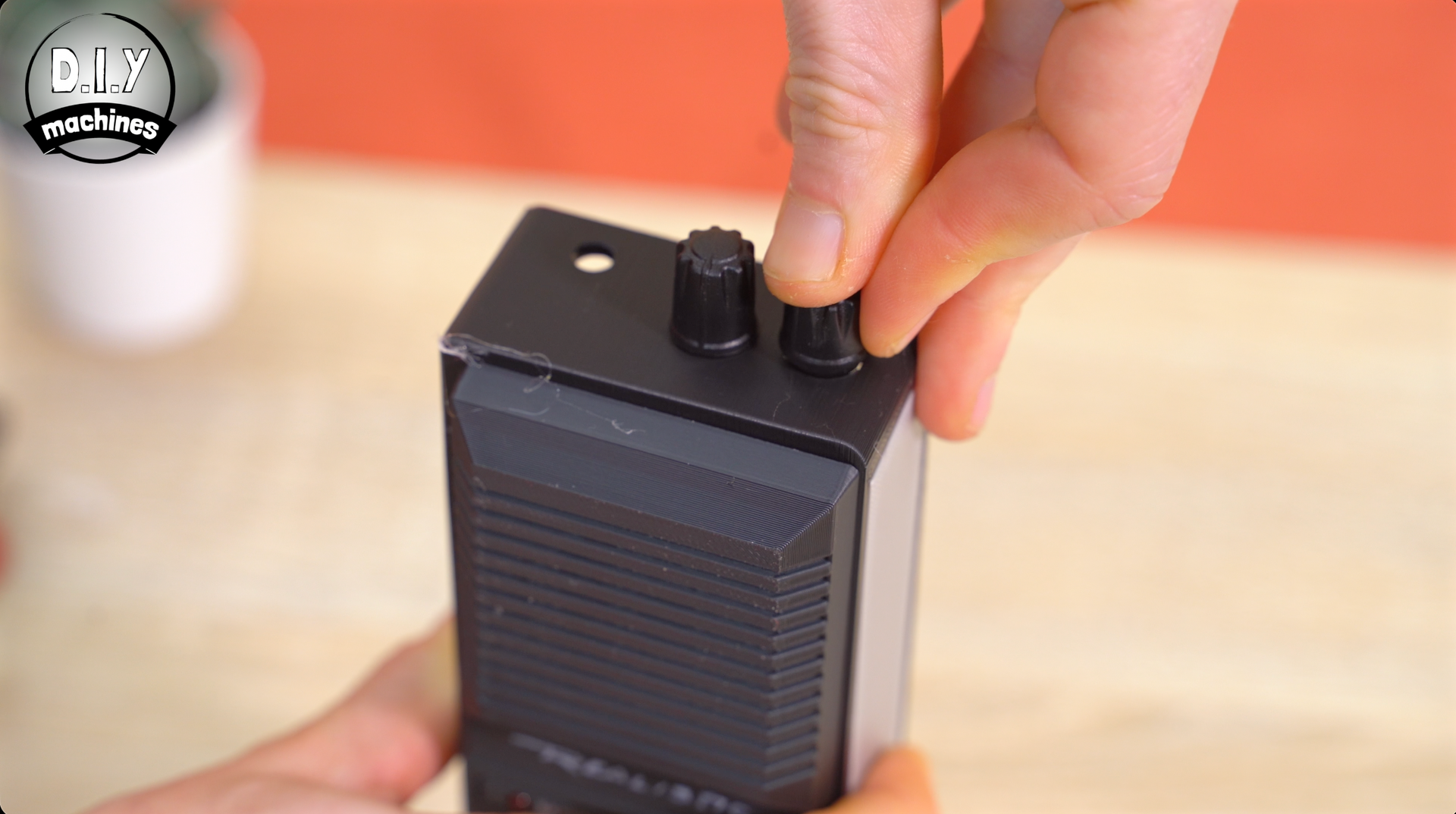
The two original knobs are then push fitted on at the top of the housing.
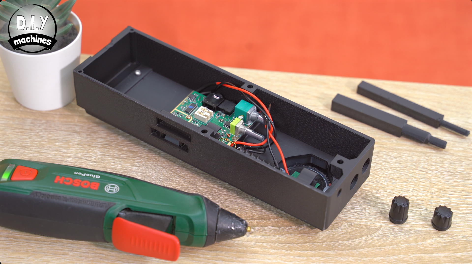
Step 11: Assembling The Battery Pack and Rear 3D Print
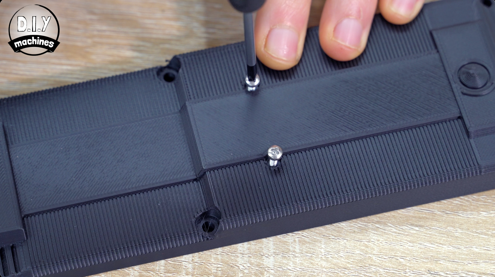
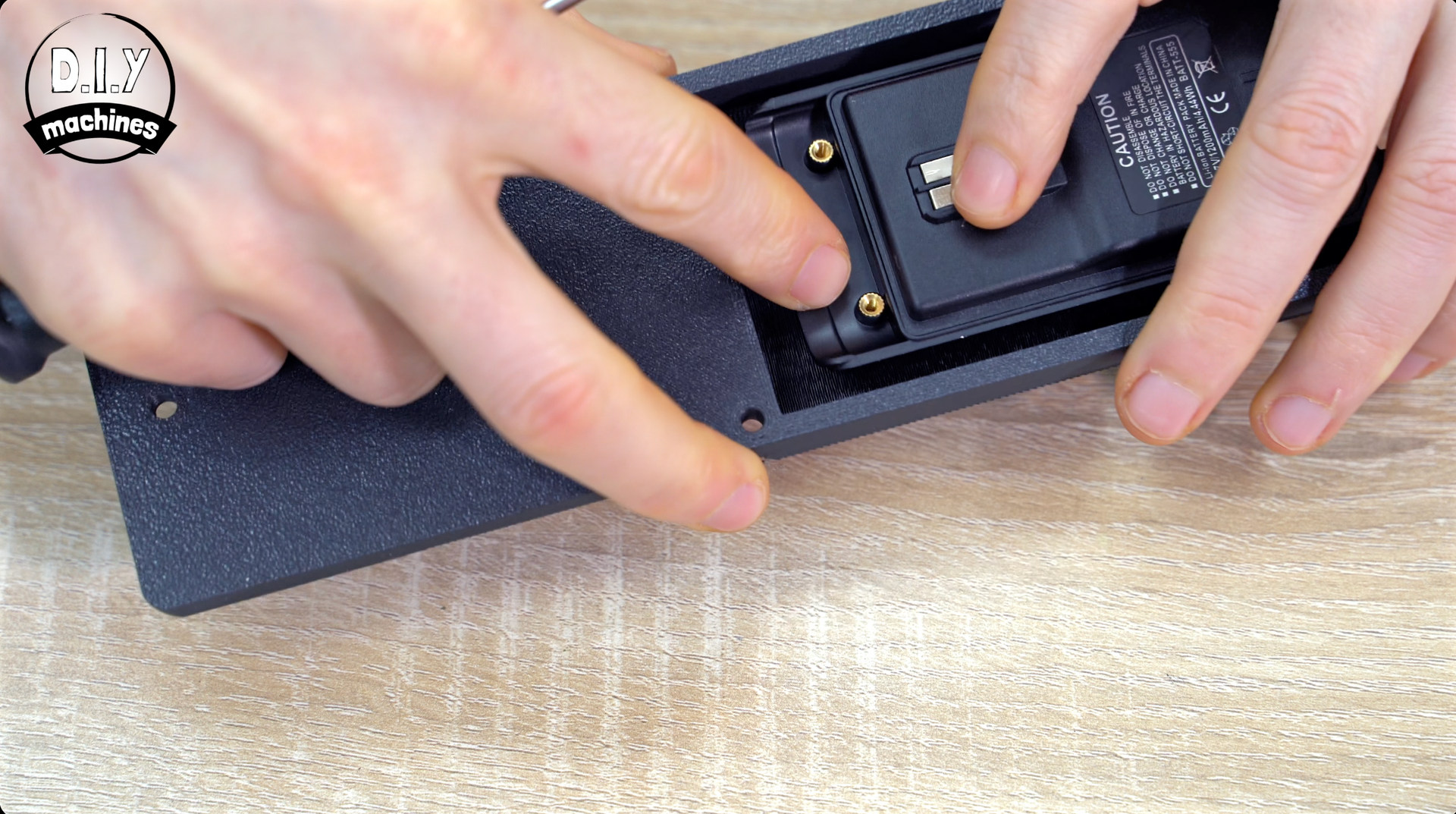
Turning our attention to the battery pack. We can print the rear of the radio (Radio Body Rear.3mf) and install the battery with two M2.5x10mm bolts.
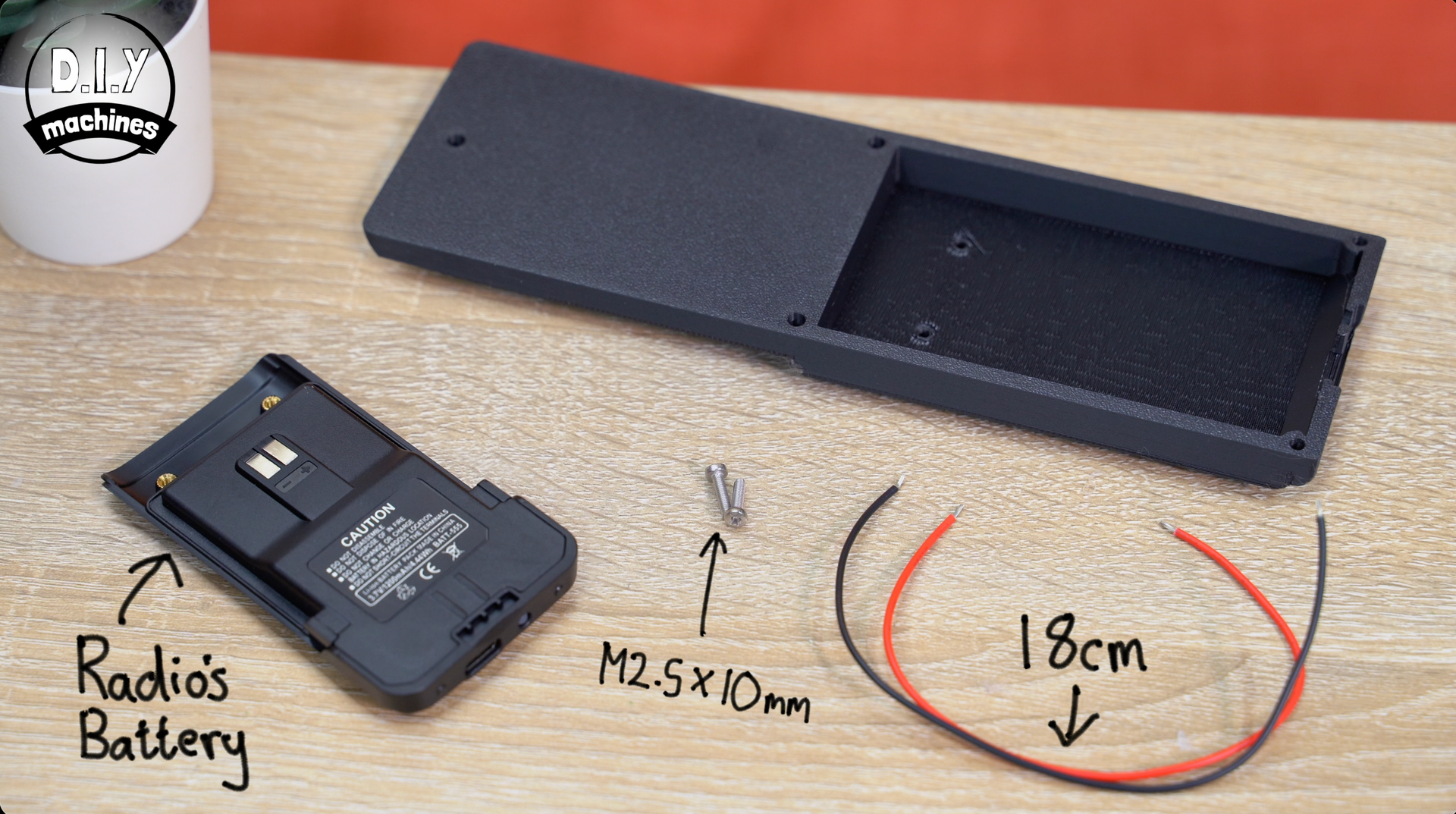
First partly screw in the two bolts from the outside of the print, then hold the battery pack in place on the inside so that it's electronic terminals are facing outwards, then finish screwing in the bolts until they grip the battery firmly into place.
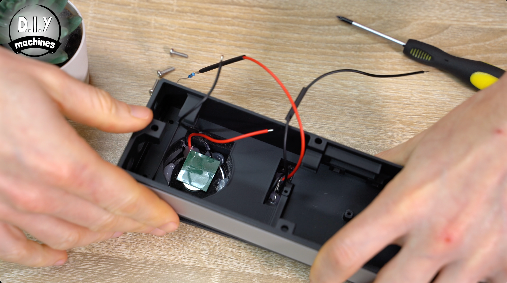
Step 12: Electrically Connecting The Battery
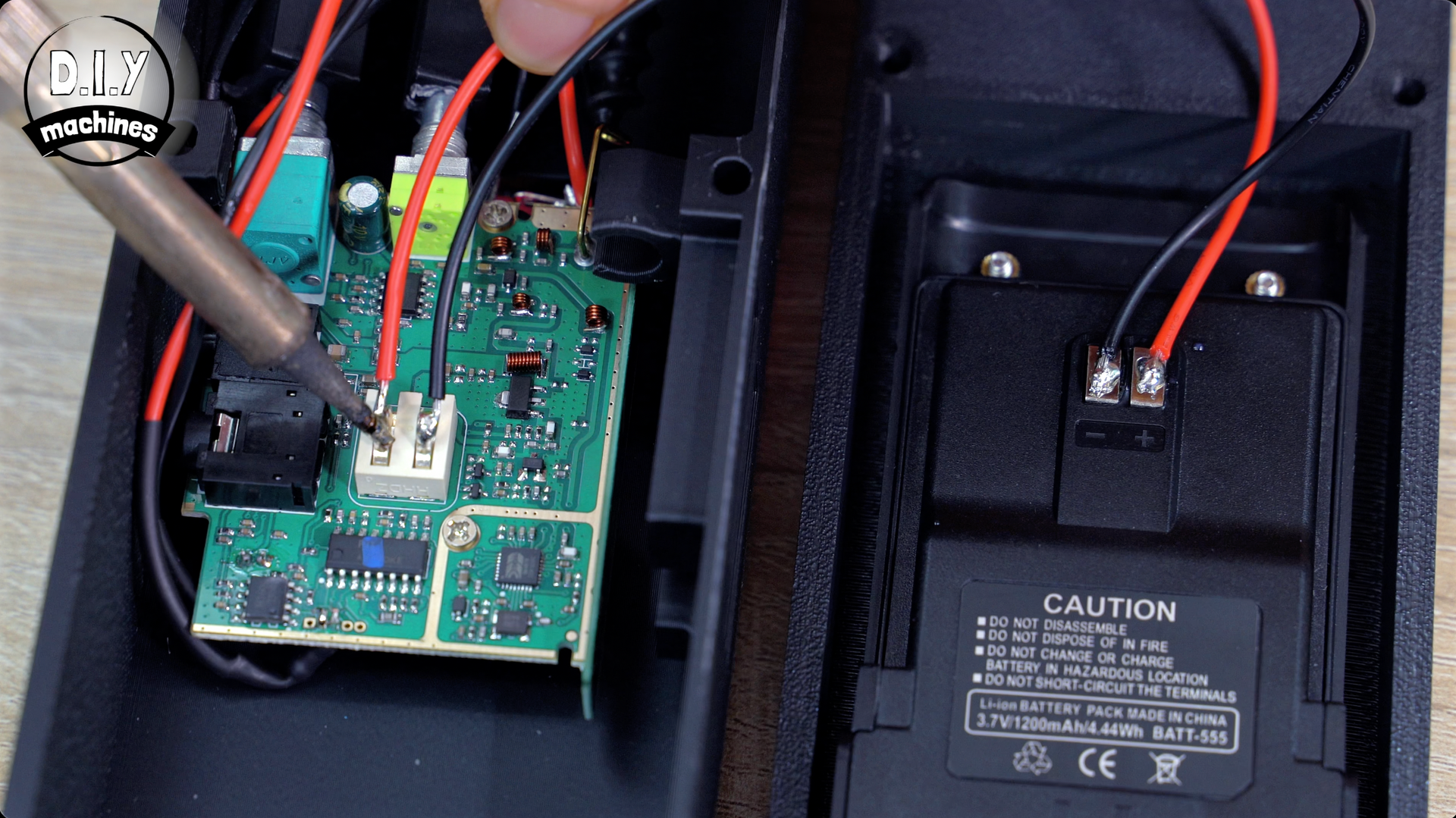
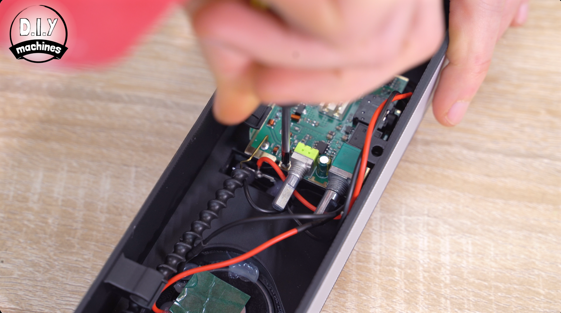
Then solder a pair of 18cm long wires between the battery terminals and terminals on the circuit board being careful of the polarity. If you lay the parts side by side as I have done in the images, the two inside connections are the negative terminals, and the two outer ones are the positive connections.
It's easier to do if you apply solder to the wires (called tinning) and to the electrical connections on the PCB and battery pack first before soldering them together.
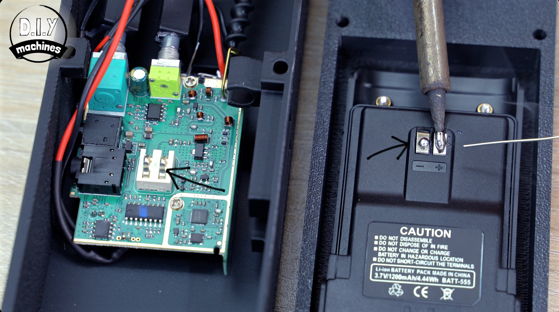
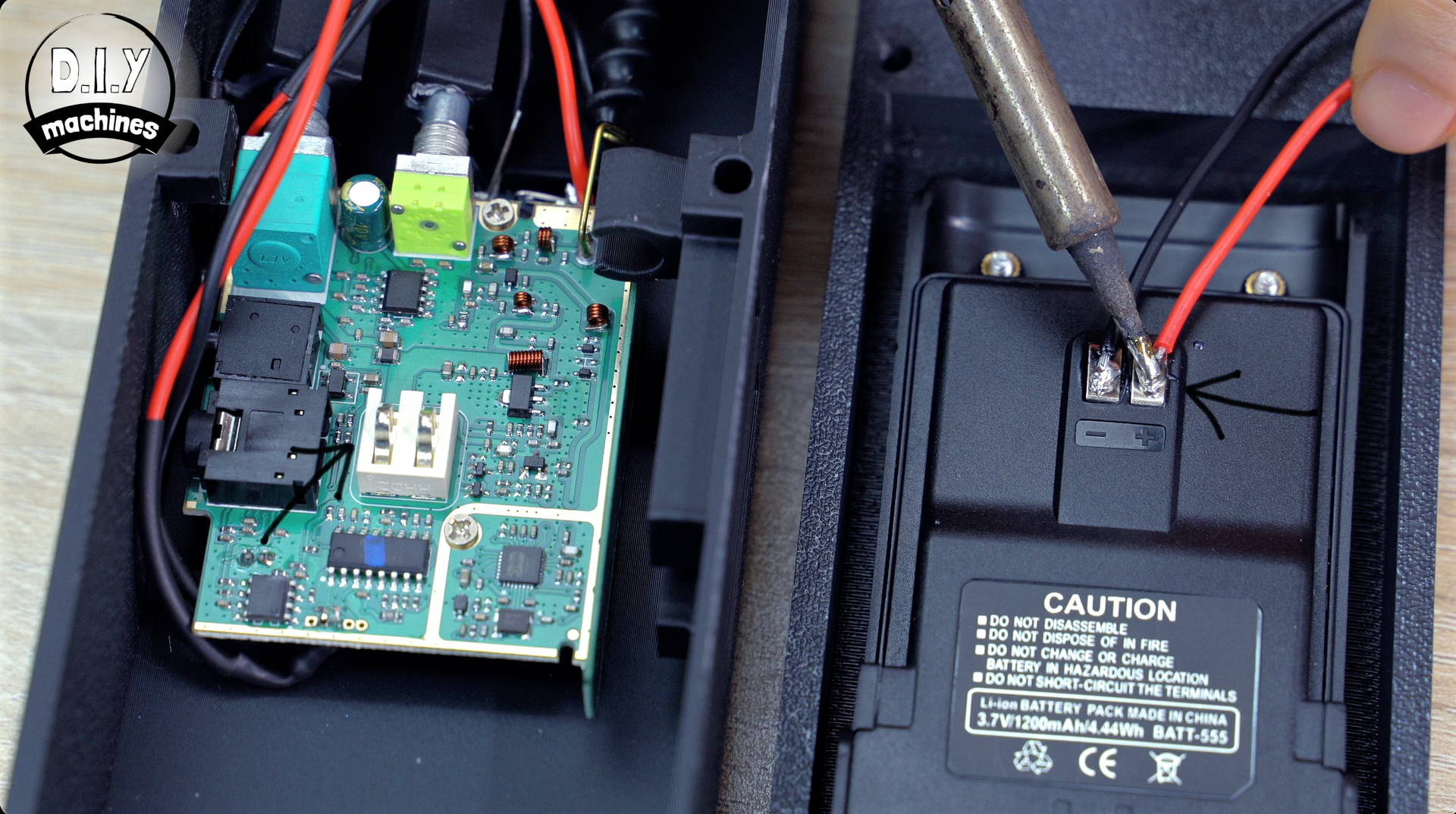
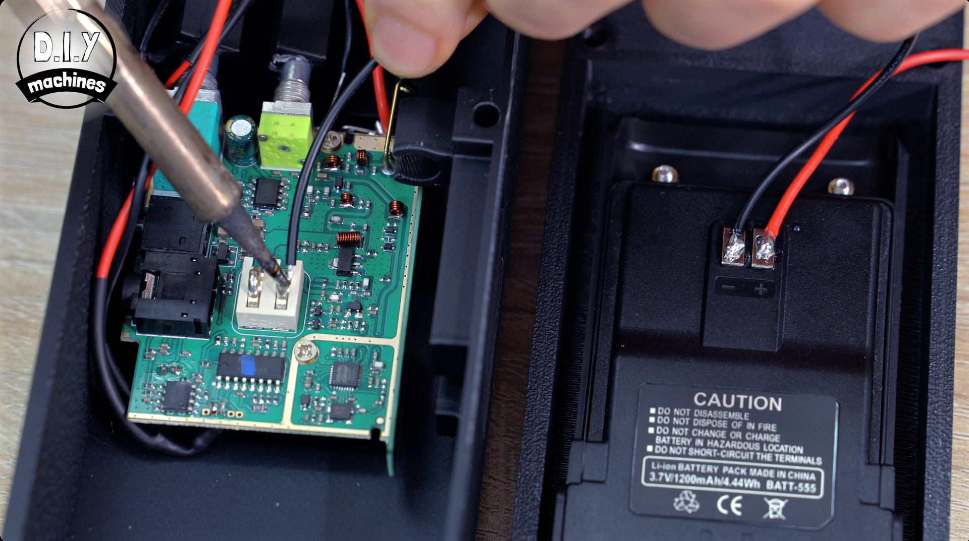
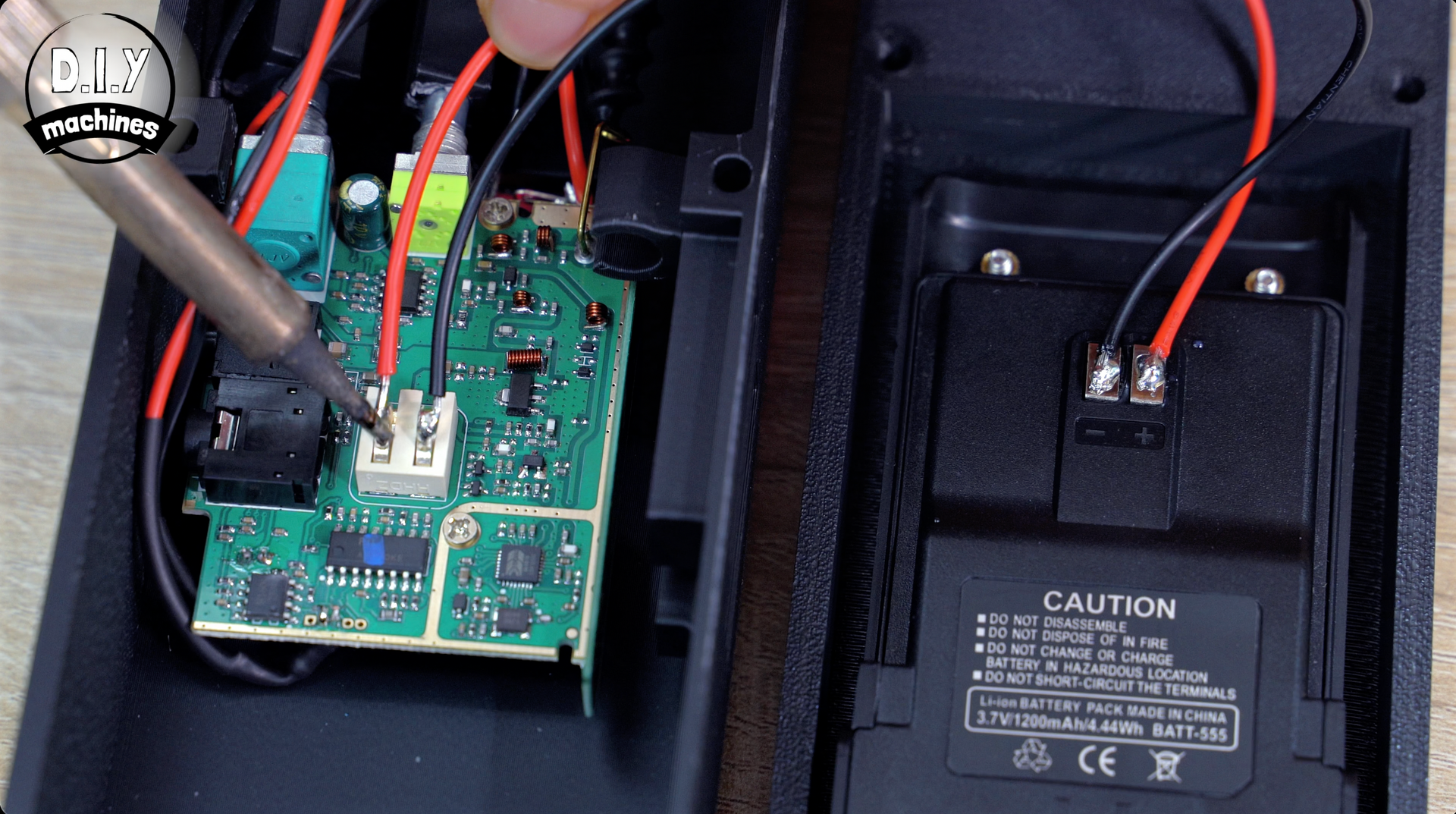
Be careful not to short the terminals or apply excess heat to the battery for too long as you may damage the battery pack and we need to be respectful of lithium batteries and their dangers.
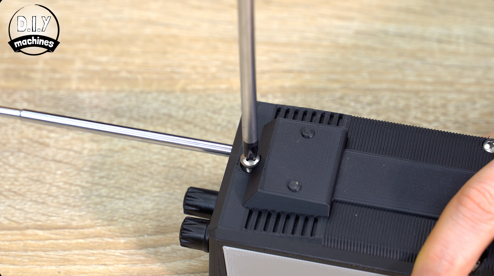
Step 13: Installing Decorative Antenna
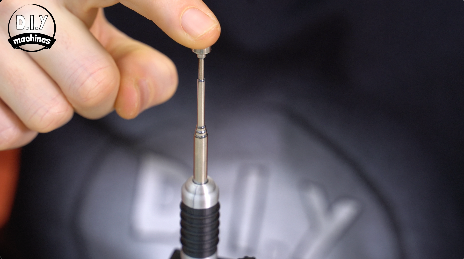
For the decorative antenna we first pop the end of the telescopic magnet (give it a good tug - it will go) and then slide the pen/rod through the hole in the assembly from the inside and then clip into place.
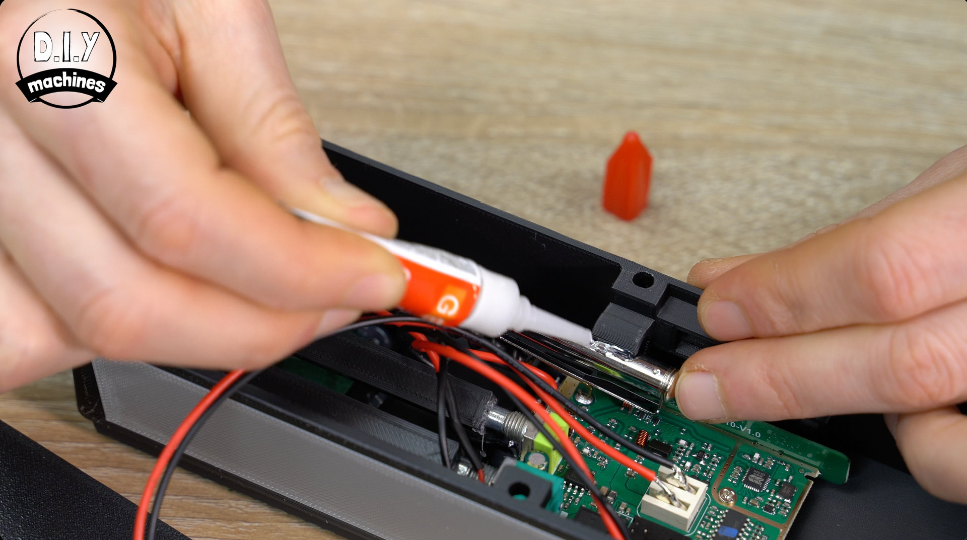
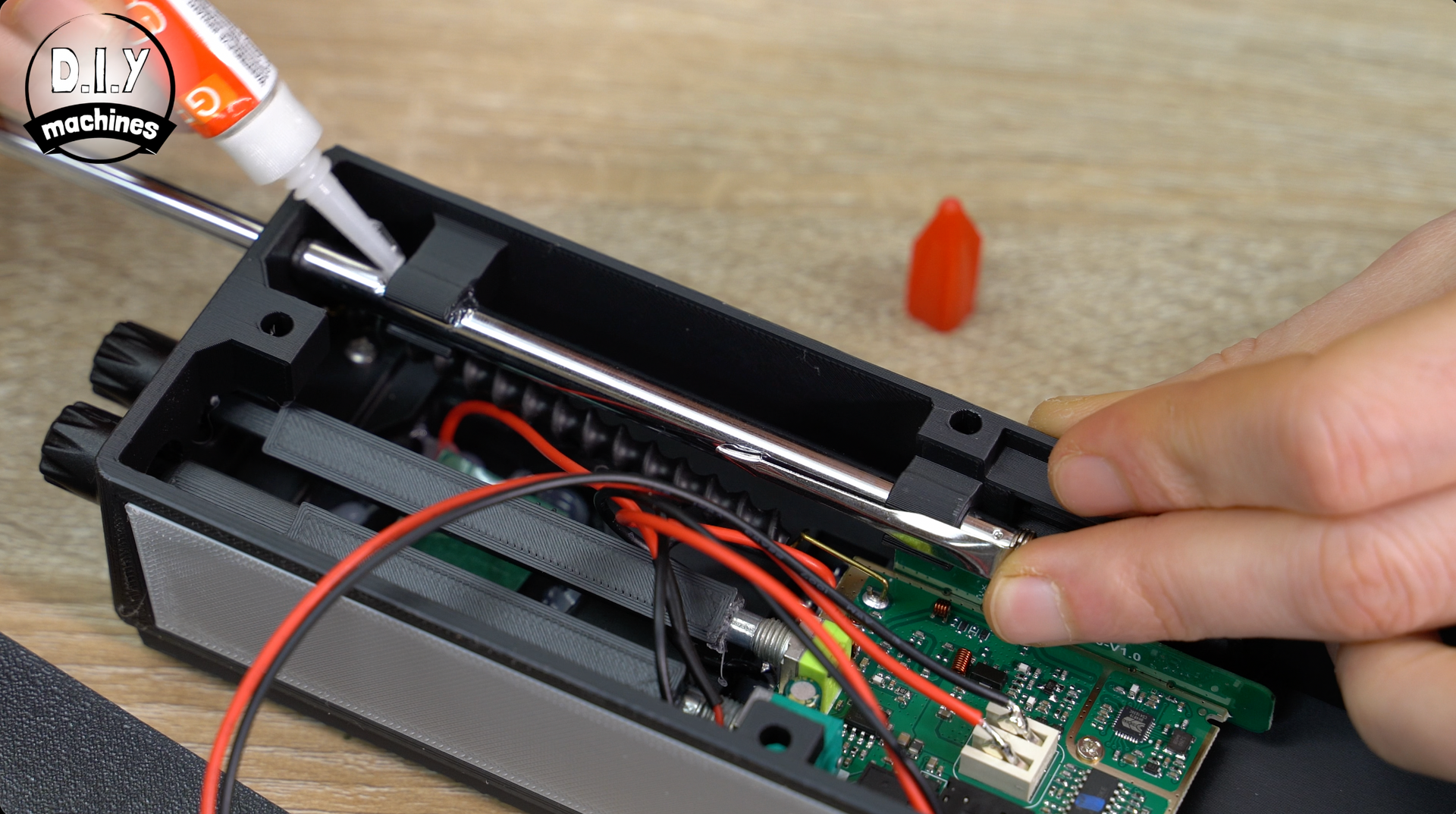
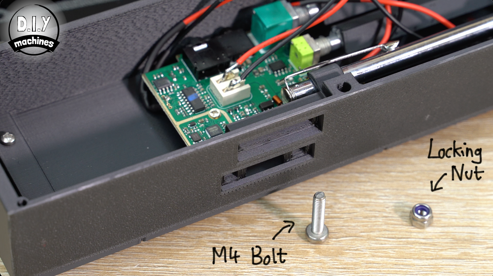
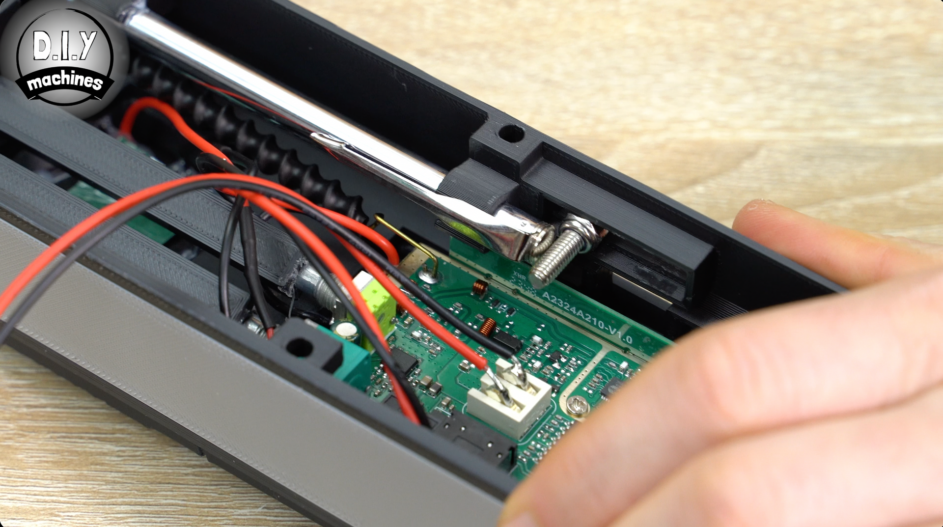
To help prevent it from sliding downwards when retracted you have two options. Either apply some glue where the two arms hold onto it, or use another M4x18 bolt and a lock nut to hold it using the adjustable slot in the side of the print. (Or to be totally secure you can always do both).
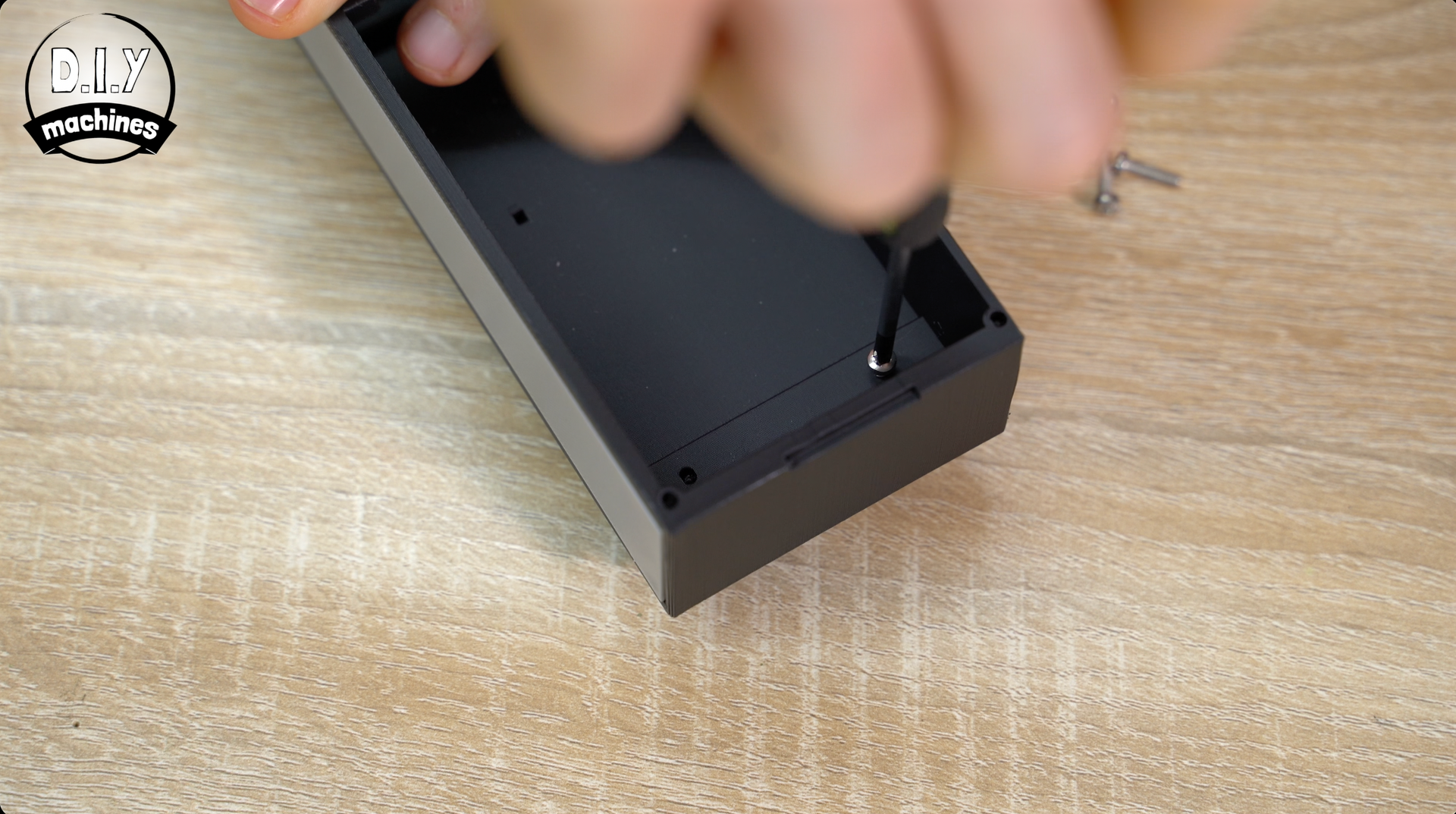
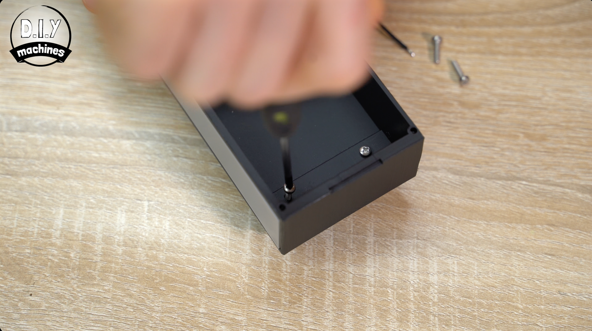
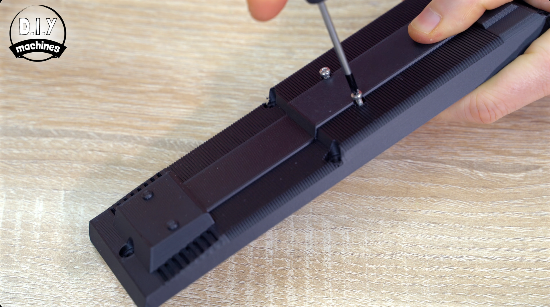
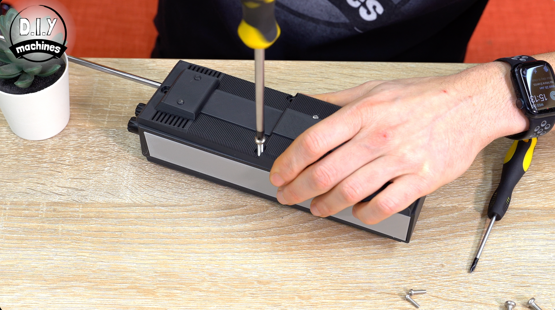
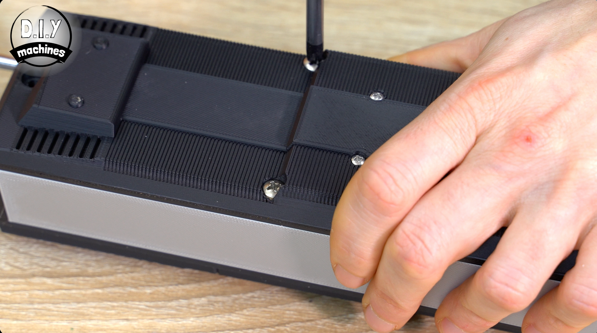
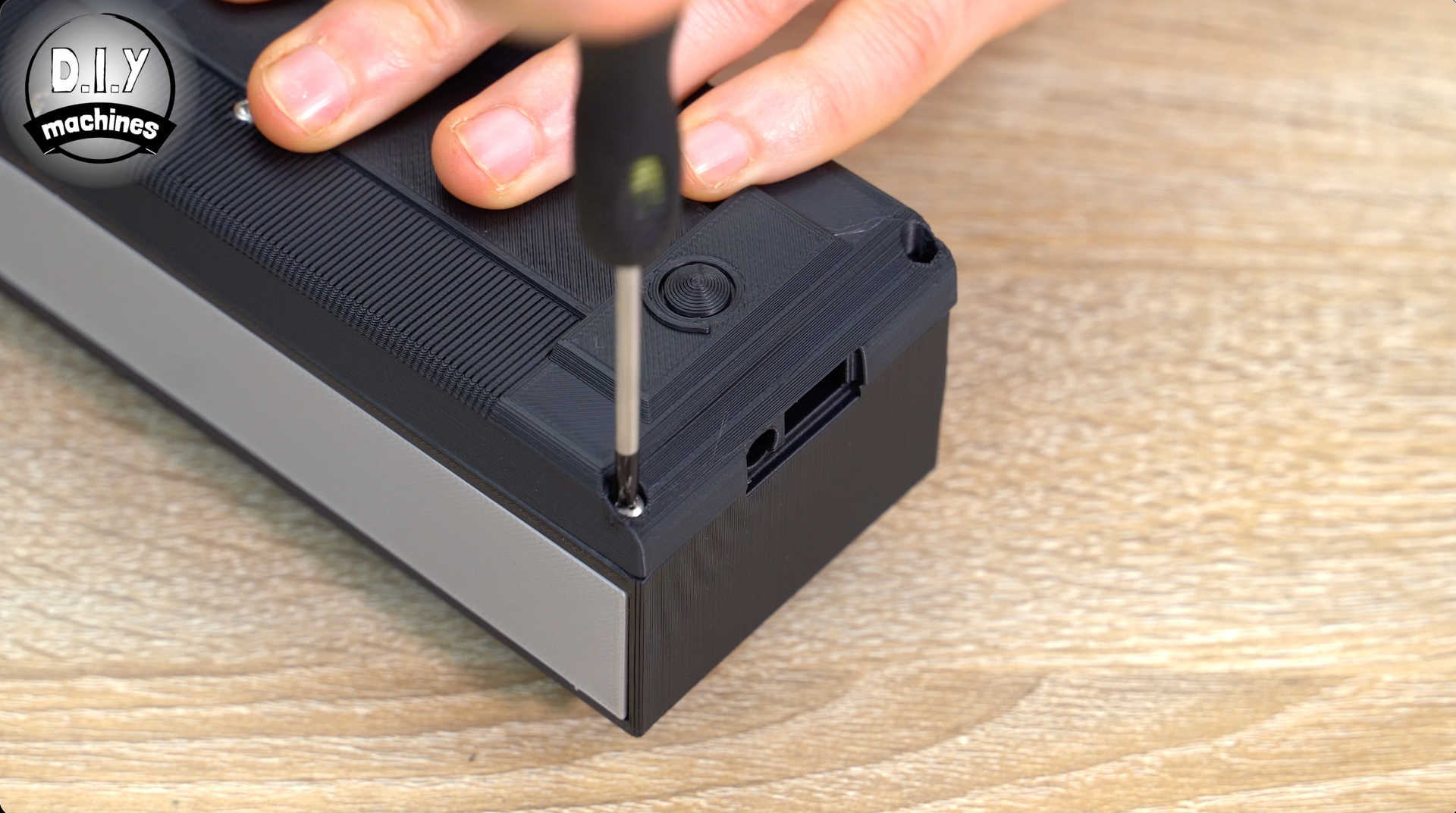
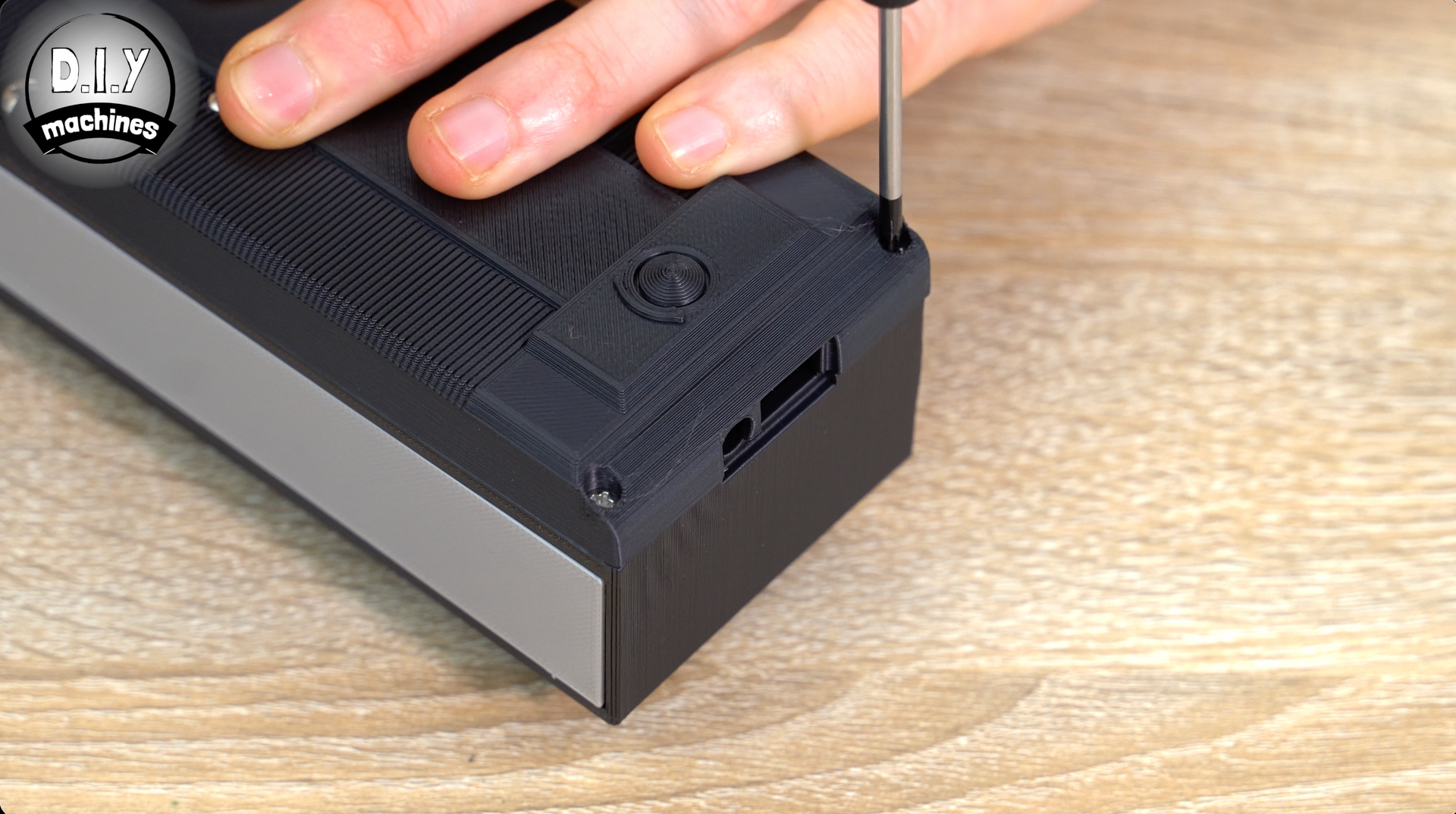
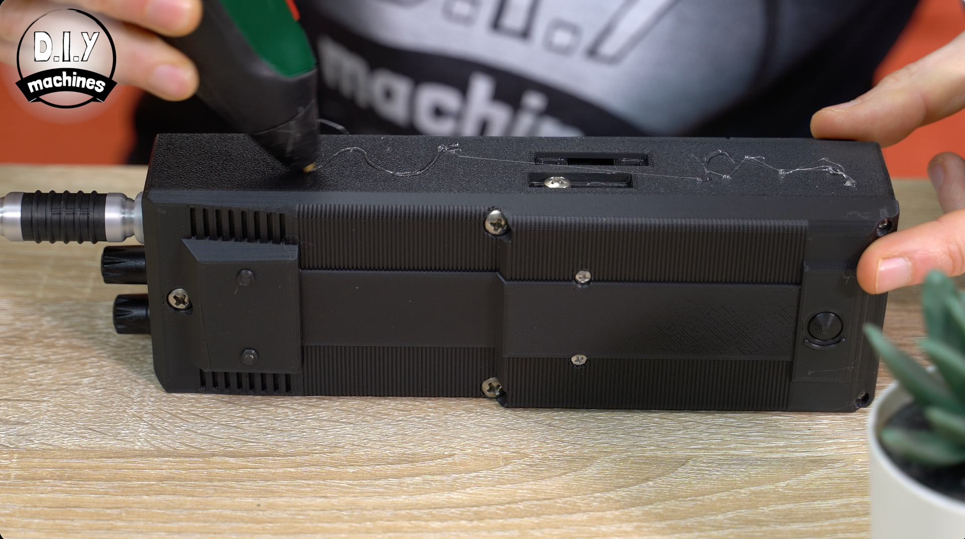
Step 14: Attaching the Rear and Top Decor
With the interior now completed let’s attach the rear of the radio using some M4x18 bolts in the top three holes, and two more M2.5x10 bolts in the bottom two holes.
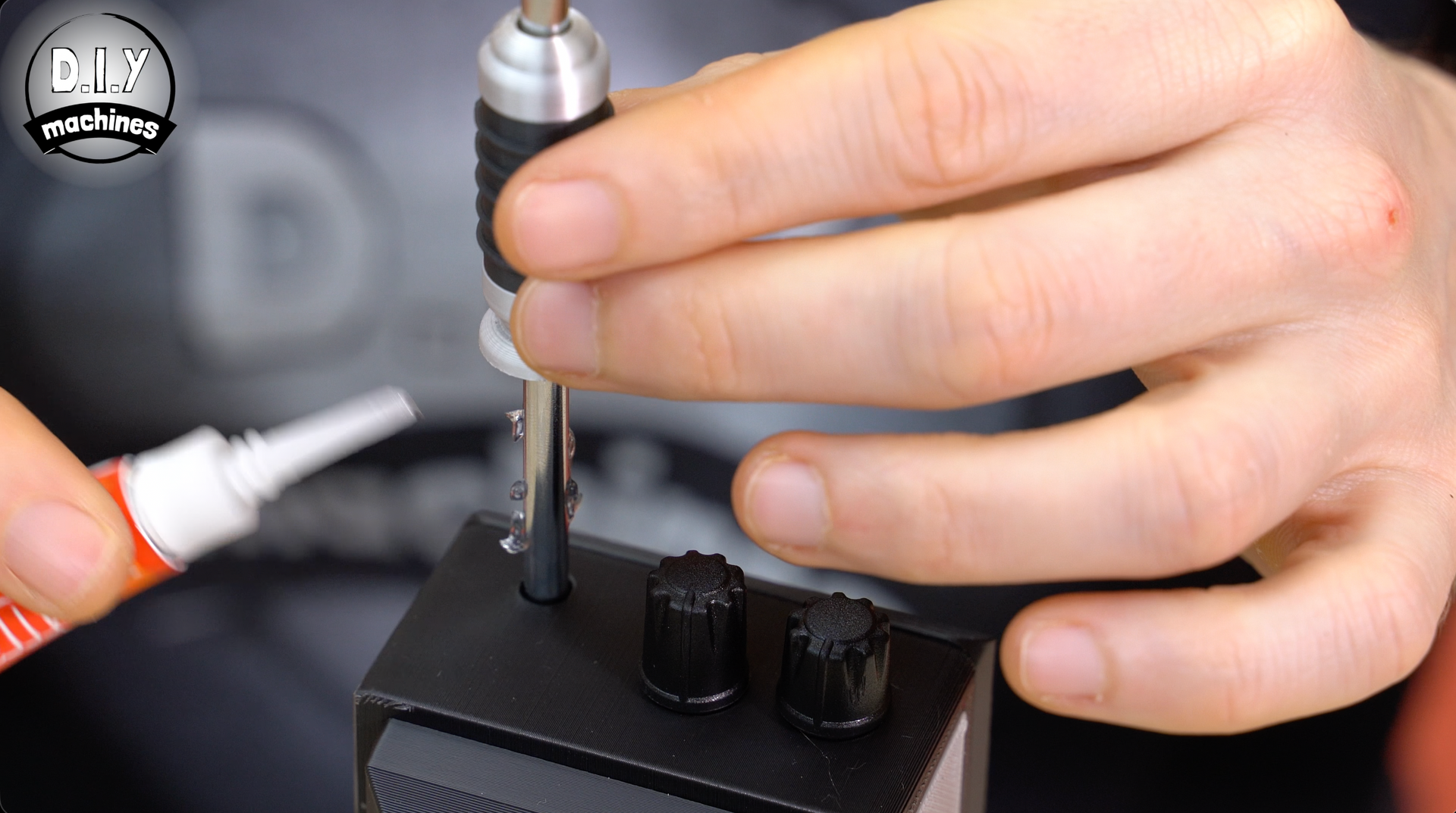
Then the decorative detail for the antenna is printed (file 'Antenna Sleeve.3mf' which can be printed on a multilateral or a single nozzle printer y changing the filament after so many layers and back again from silver, to black, then silver). This is slid over the metal antenna and glued into place at the base. The top of the rod can then be carefully re-inserted.
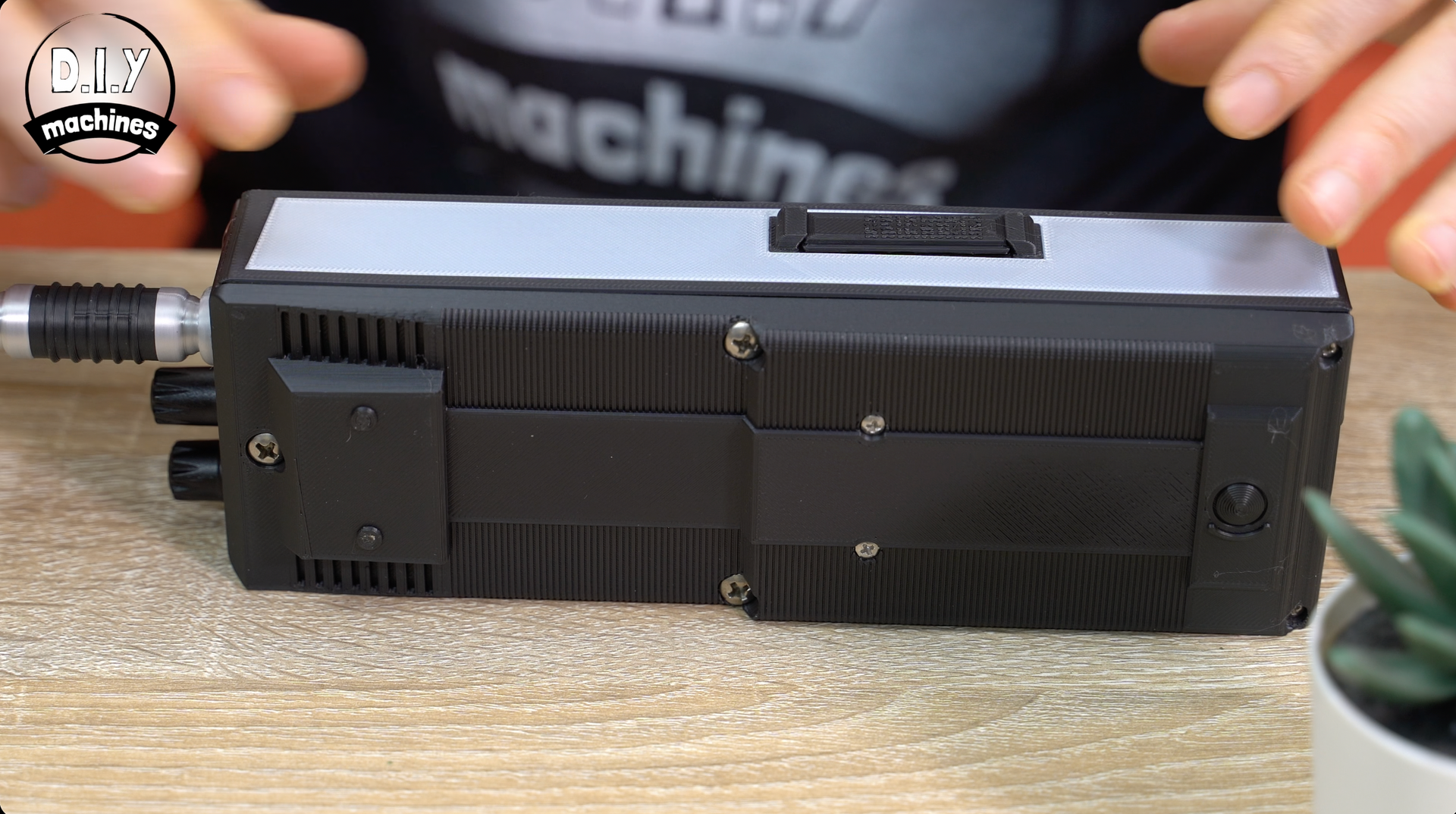
Step 15: Assembling the Left Hand Side and Transmit Button
Now that we don’t need access to the bolt slot on the side we can also complete the LH side of the radio.
Multi material printers need print: 'LH Side Panel - Multi.3mf' and standard printers should print ‘LH Side Black - Single.3mf’ and glue in place the second silver side with holes we printed earlier.

For the buttons on the side of the radio used to start the transmission, I have included a variety of depths you can print. Start off by printing the 15mm deep button and inserting into the side piece - this should suite most builds. Hold it in place (inside of the side panel) against the radio side and see if you click and release the buttons.
Turn on the radio and see if the button engages the transmission when pressed, and stops when released. If it does not, try a longer or shorter button. Models for depths 14mm through to 17mm are available in increments so you can find the best fit for your build.
When the correct button has been found we can glue the side panel onto the radio ensuring you don’t get any adhesive near and certainly not onto the button itself.
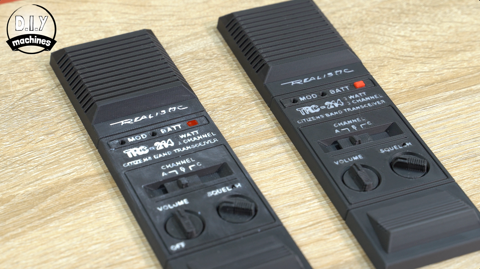
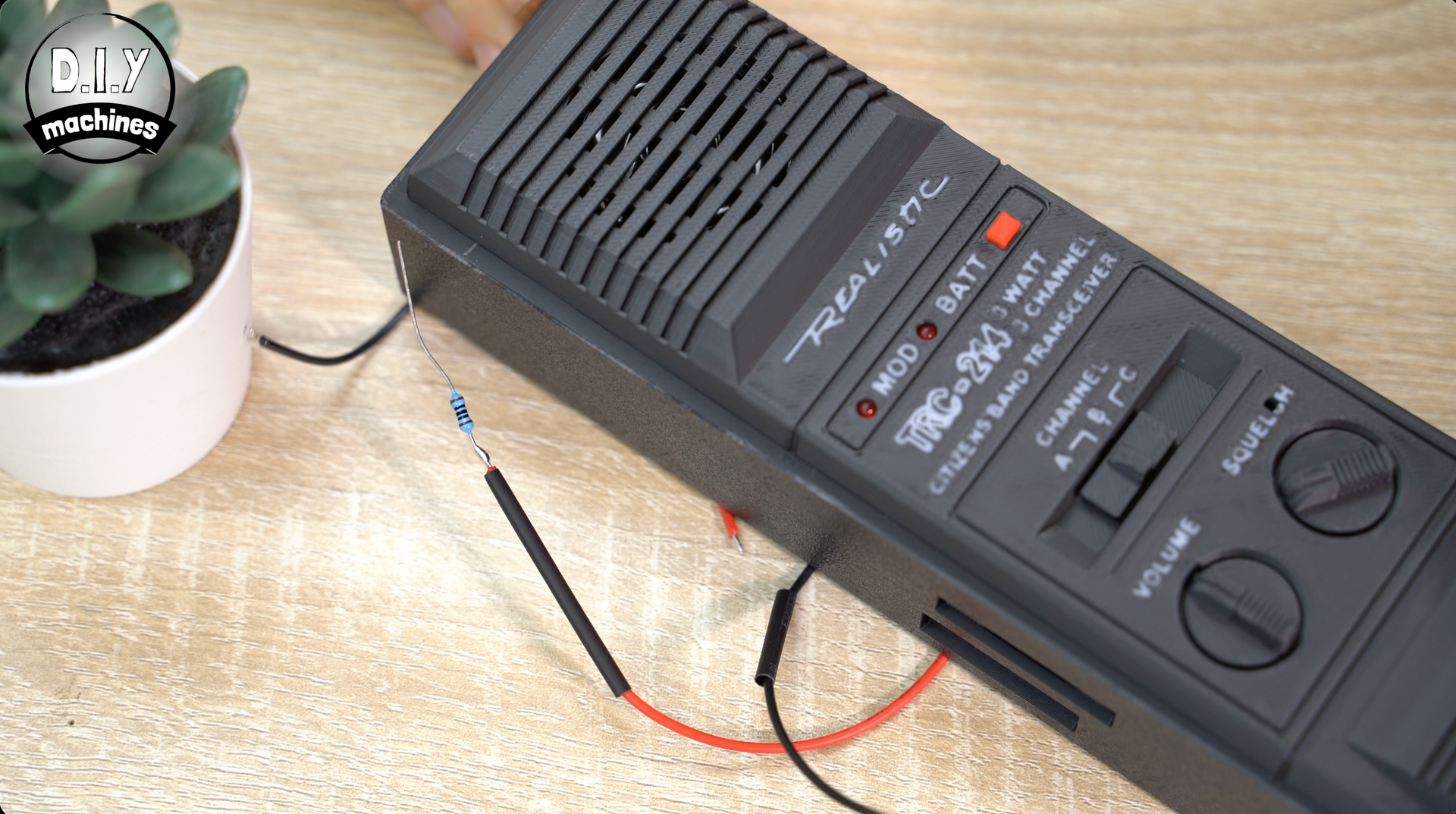
Project Complete!
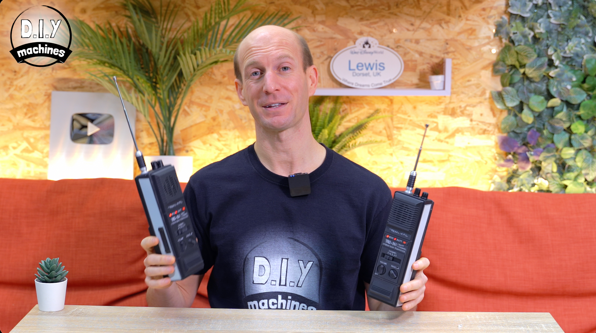
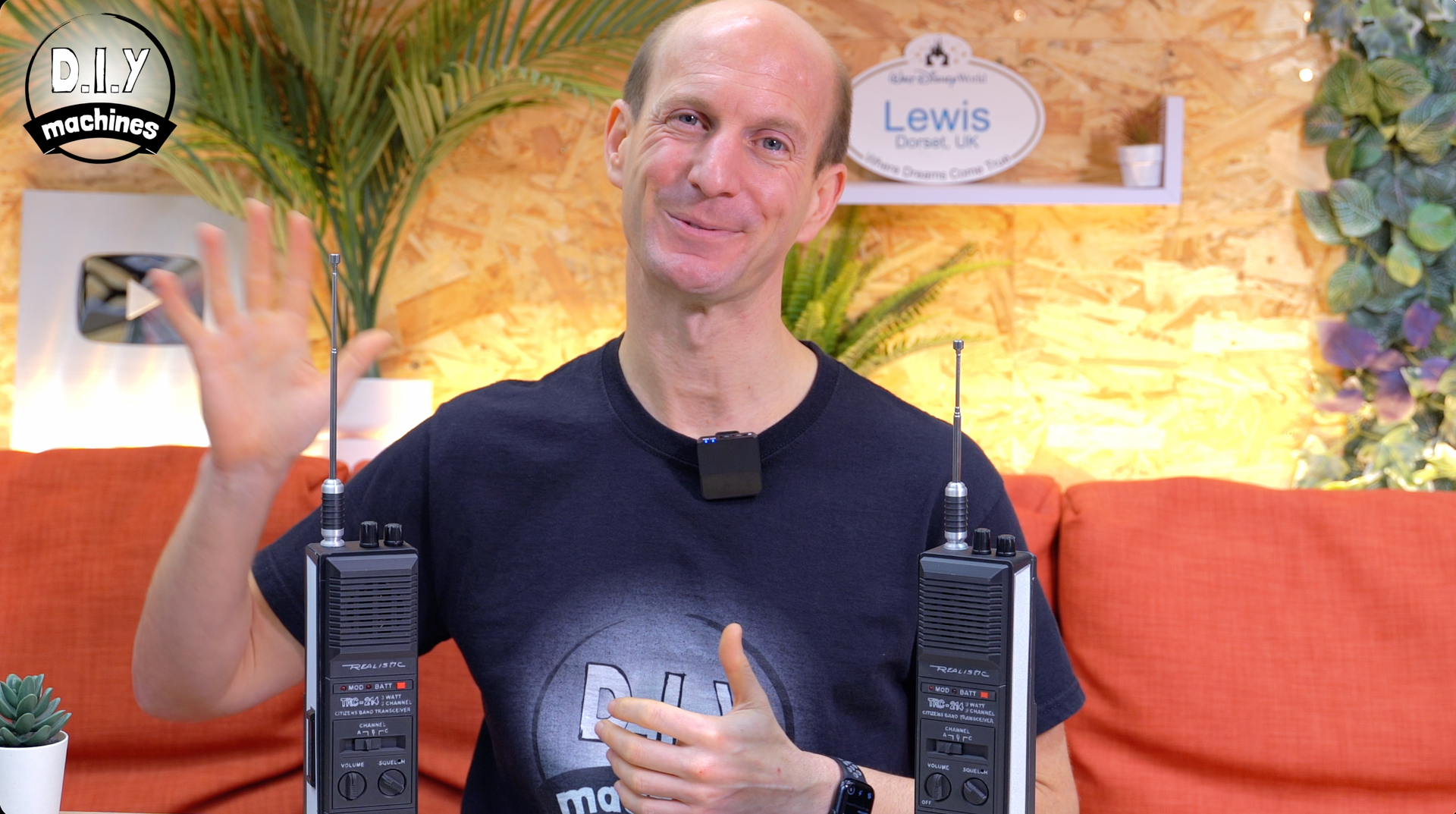
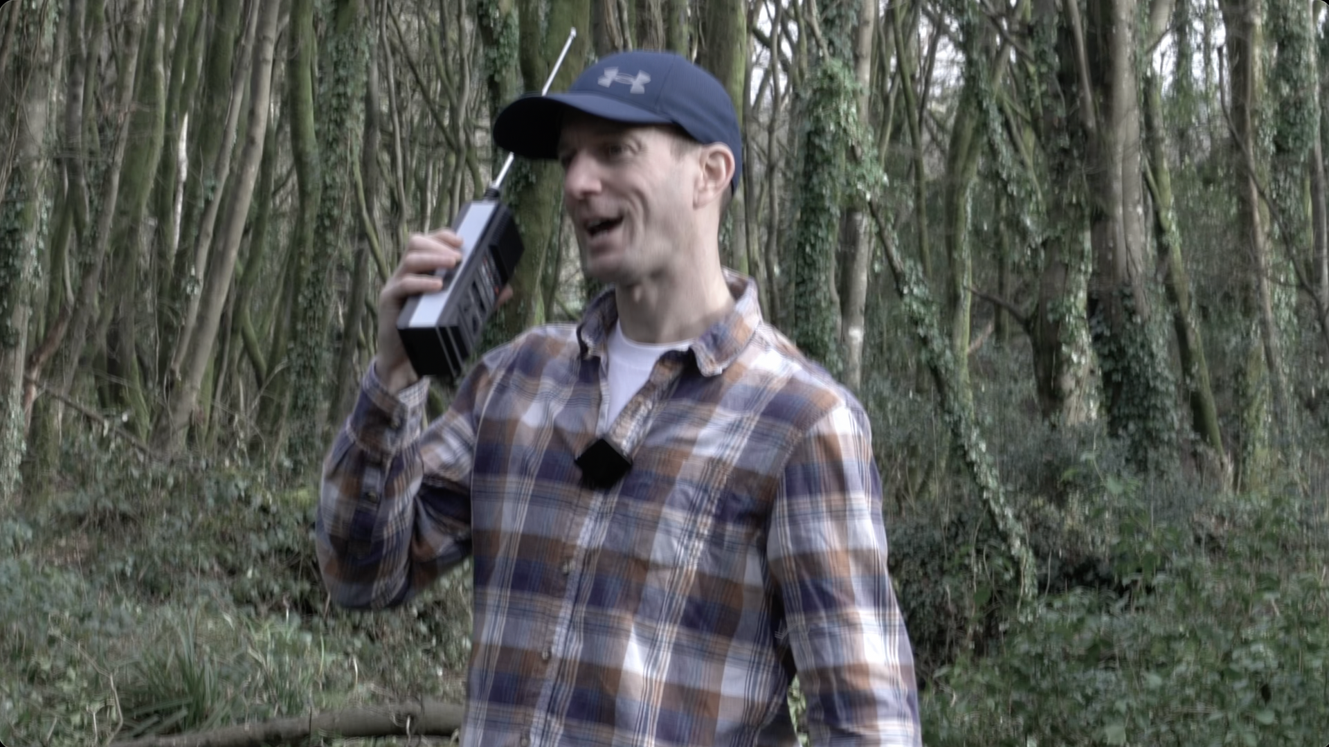
There we go! If you bought a pair of radios, feel free to convert both or keep one in its original form factor. They’ll still be able to communicate with each other and similar brands of radios on the same frequencies.
To recharge your radio, simply connect a USB C cable to the port at the bottom.
Thank you so much for reading through to the end. If you’d like to help me make, document and share more projects like this please consider becoming a YouTube Member or Patreon.
https://www.youtube.com/@DIYMachines/membership
https://www.patreon.com/c/diymachines
Don’t forget to like and subscribe to the channel on Youtube .
Until the next video - do some good and chow for now. :)
Community:
Discord server for this project: (A great place for questions and advice).
There is a comments section at the end of this page where you can also engage with other makers. However I do find the Discord community more active. :)