TSX0108E - Logic Level Converter
A logic level shifter is a great tool to have in your arsenal as a maker. They are fantastic at helping to bridge the gap between 3.3v logic devices (such as Raspberry Pi's and some sensors) and 5v logic devices such as Arduino Uno's.
In this post I'll explain the TXS0108E shifter by Texas Instruments. It's cheap enough to have several to hand for when you need it next.
To follow along with the example project in the video you will need a few items, the links automatically redirect you to right item on your local Amazon site:
- TXS0108E Logic Level Shifter: https://geni.us/TXS0108E-Shifter
- Raspberry Pi: https://geni.us/RaspberryPiV4
- Arduino Uno: https://geni.us/ArduinoUno
- Jumper wires: https://geni.us/JumperWires
- Breadboard: https://geni.us/MiniBreadboard
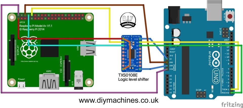
Wiring Diagram:
Mini Make - Hands on example project:
Once you have wired together the project as shown in the wiring diagram above we can prepare the software on the Raspberry Pi and the Arduino.
Preparing the Arduino:
The Arduino should be connected to your computer via USB and then use the free Arduino IDE (https://www.arduino.cc/en/software) to upload this code to it after selecting the correct board type and port:
Preparing the Raspberry Pi:
You will need to install an image of Raspberry Pi OS on your SD card if you have not already done so. I recommend using the official Raspberry Pi Imager to install the latest version of the OS. The software can be downloaded for free from the Pi Foundation: https://www.raspberrypi.org/software/
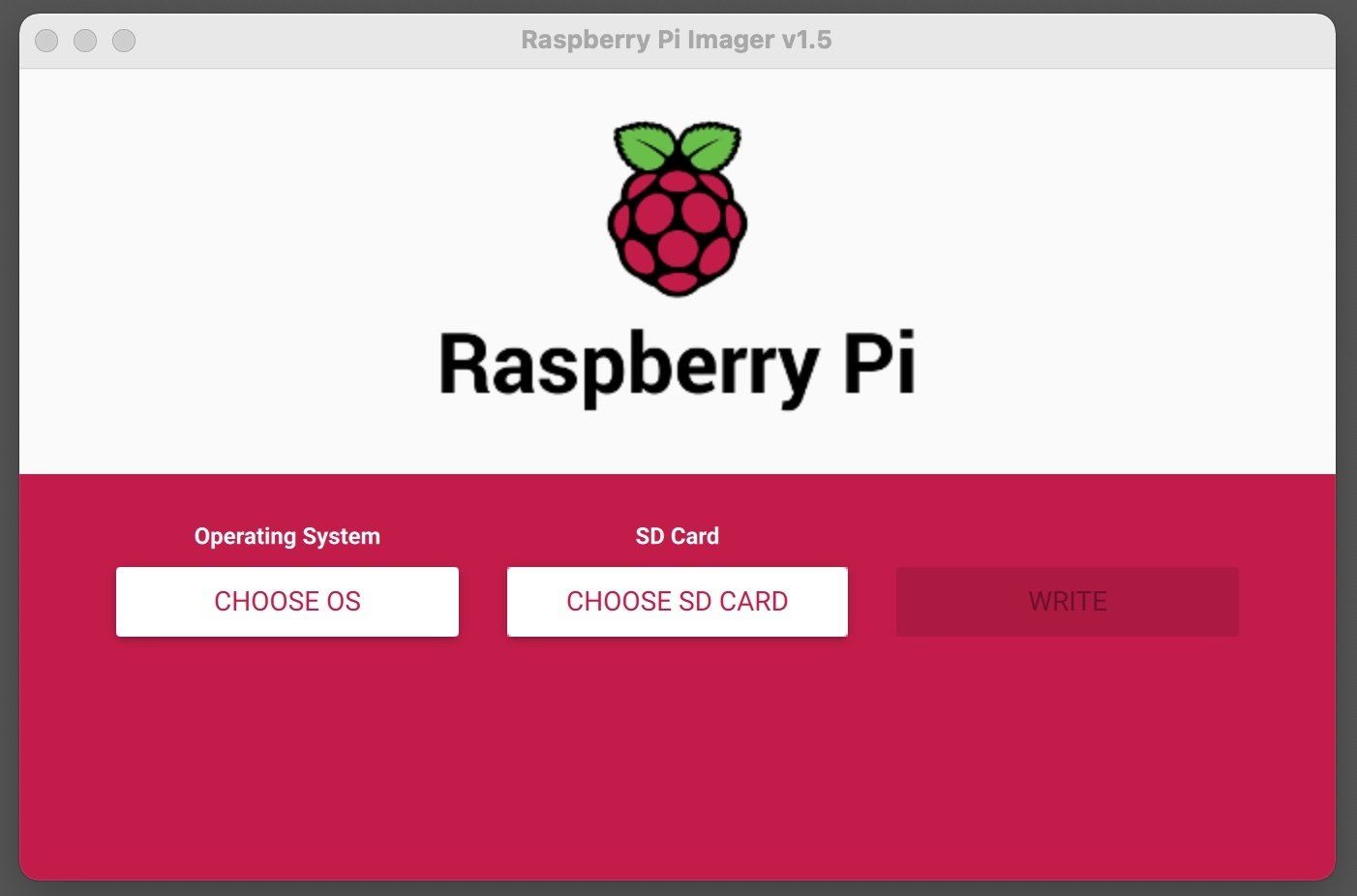
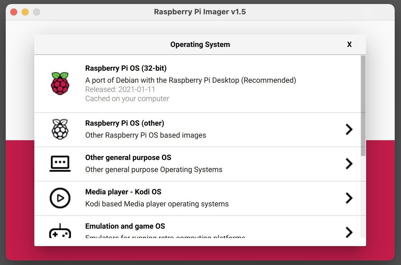

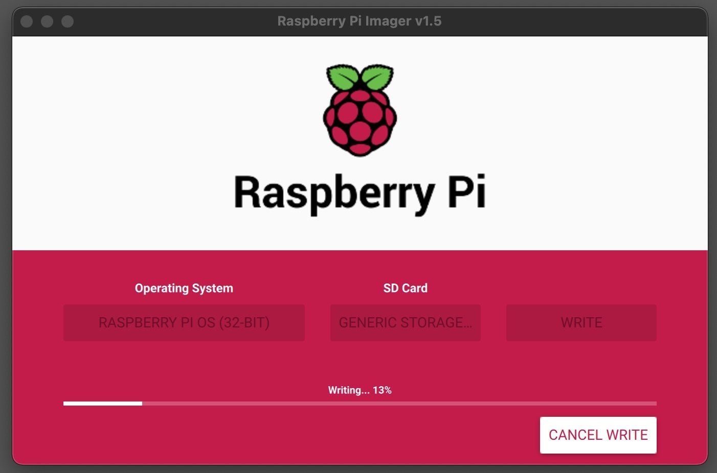
After installation is complete, open the program a choose the Raspberry Pi OS. If you have not downloaded it before the program will download it automatically for it and cache it for future installs. Insert a micro SD card of 4GB or higher which you don't mind being erased and then press 'WRITE'. This might take a little while to be written to the card and verified. But once complete you will need to remove and then reinsert the micro SD card so that it mounts itself as 'BOOT' on your computer.
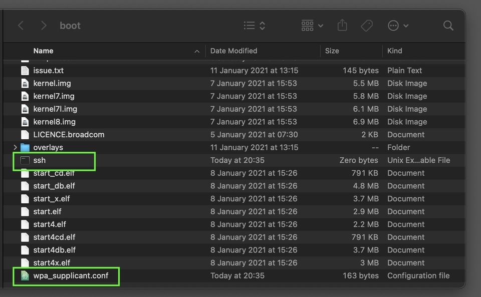
We will add two files to the boot partition to accelerate the setup of the Pi. One will configure SSH and the other your wifi credentials.
For the wifi credentials you will need to create a new file on the boot partition named text 'wpa_supplicant.conf'. In this text file past the following:
Don't forget to replace YOURSSID and YOURPASSWORD with the correct details for the wifi connect you want your Pi to connect to. You should also set the correct country code if you are not in the US. For me here in the UK it should be set to GB. See here for a list of other country codes: https://en.wikipedia.org/wiki/ISO_3166-1_alpha-2
To enable SSH on the Pi we just need to create a blank file with the name ssh on the boot drive.
Once you have created both of these you can safely remove the micro SD card and boot it on your Raspberry Pi.
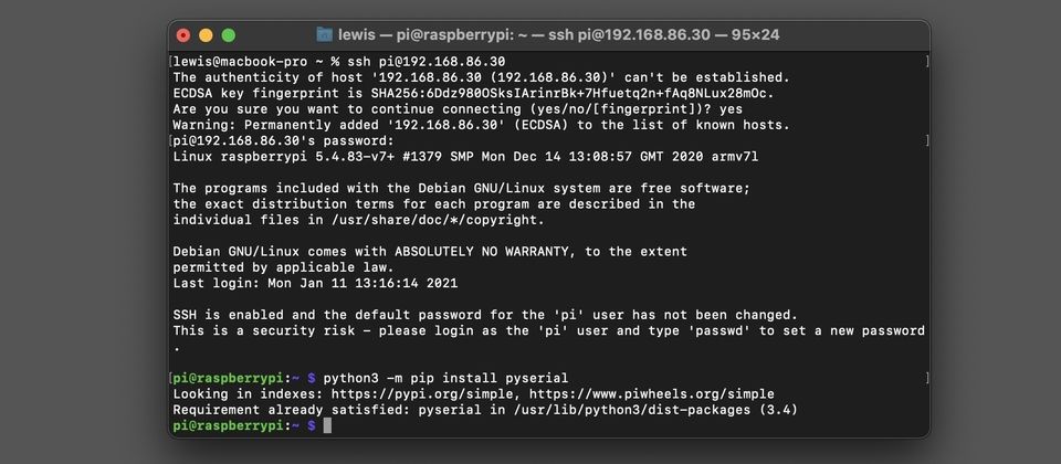
Configuring the Raspberry Pi
Connect to the Pi via SSH after it has completed booting. We will first need to install a popular serial library which we will be using later. Do this with the command: 'python3 -m pip install pyserial' at the terminal. You may find you already have it installed.
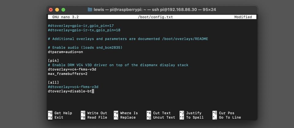
Next we need to redirect the full UART from the Bluetooth to the GPIO pins on the Raspberry Pi. This just requires a couple of amendments to some text documents.
To disable the bluetooth edit the file '/boot/config.tx' by typing
sudo nano /boot/config.txt
in the terminal. Scroll down to the end of the document and at the very end under '[all]' add a new line which reads:
dtoverlay=disable-bt
To save the changes and exit type CTRL+X on the keyboard, followed by 'Y' to confirm that you want to save your changes and then press ENTER to confirm again.
We also need to disable the serial console. For this you need to edit the /boot/cmdline.txt file. Do this by using the command:
sudo nano /boot/cmdline.txt
Find the following text and remove it: 'console=serial0,115200'

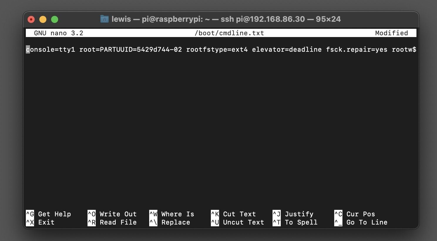
Exit the editor as you did before, saving your changes, and then reboot the Raspberry Pi:
sudo reboot
After the Pi has rebooted you should find that when you run the command ls -l /dev/serial* you see that serial0 port points to ttyAMA0 as shown below:

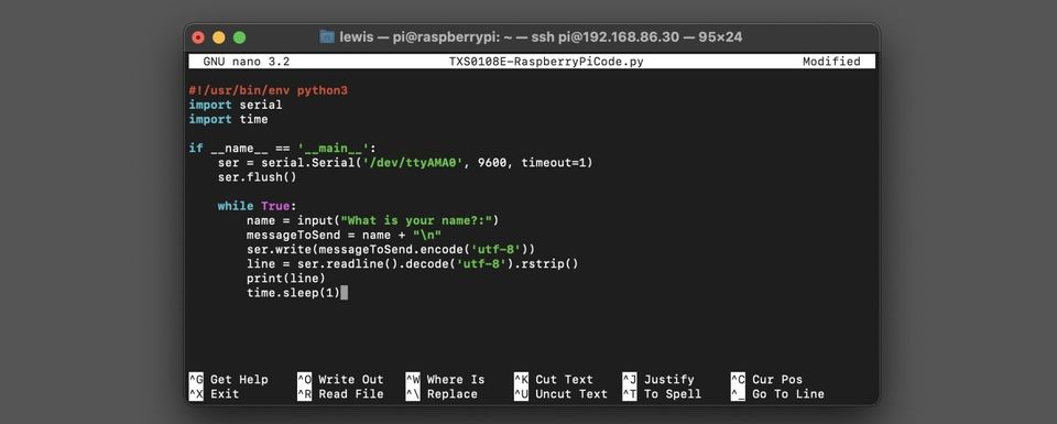
Adding the script to the Pi is as simple as creating a new document named 'TSX0108E-RaspberryPiCode.py/ by running the command: sudo nano TXS0108E-RaspberryPiCode.py
Into this document past in the filling small Python script:
Run the test
We're ready now to test our code and see the TSX0108E logic level converter in action. To do this, check all your wiring is in place according to the wiring diagram towards the top of this page. You should only have USB power connected to the Raspberry Pi - the Arduino is being powered by the Pi.
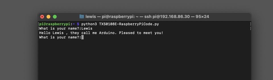
On the Raspberry Pi run: python3 TXS0108E-RaspberryPiCode.py
Answer the Pi's question with your name. The Pi then passes this to the Arduino via its serial communication with the logic level translator taking care of the required voltages for both devices. The Arduino then modifyies the string before returning it back to the Pi for it to display in the terminal - proving that the converter works in both directions.
Comments: