DIY 3D Printable Motorised Camera Slider
The Ultimate 3D Printed Robotic Camera Slider (Step-by-Step Guide)
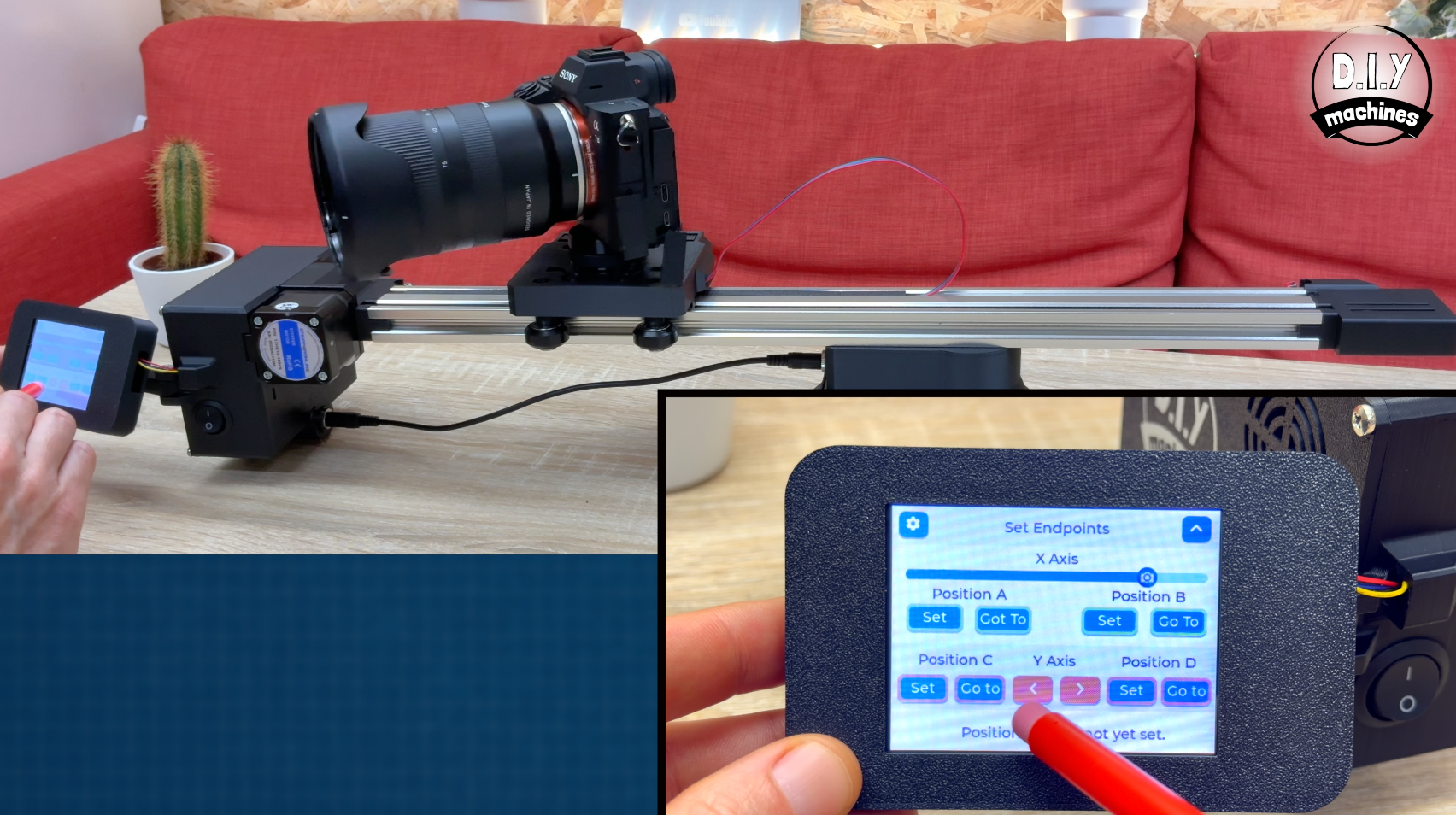
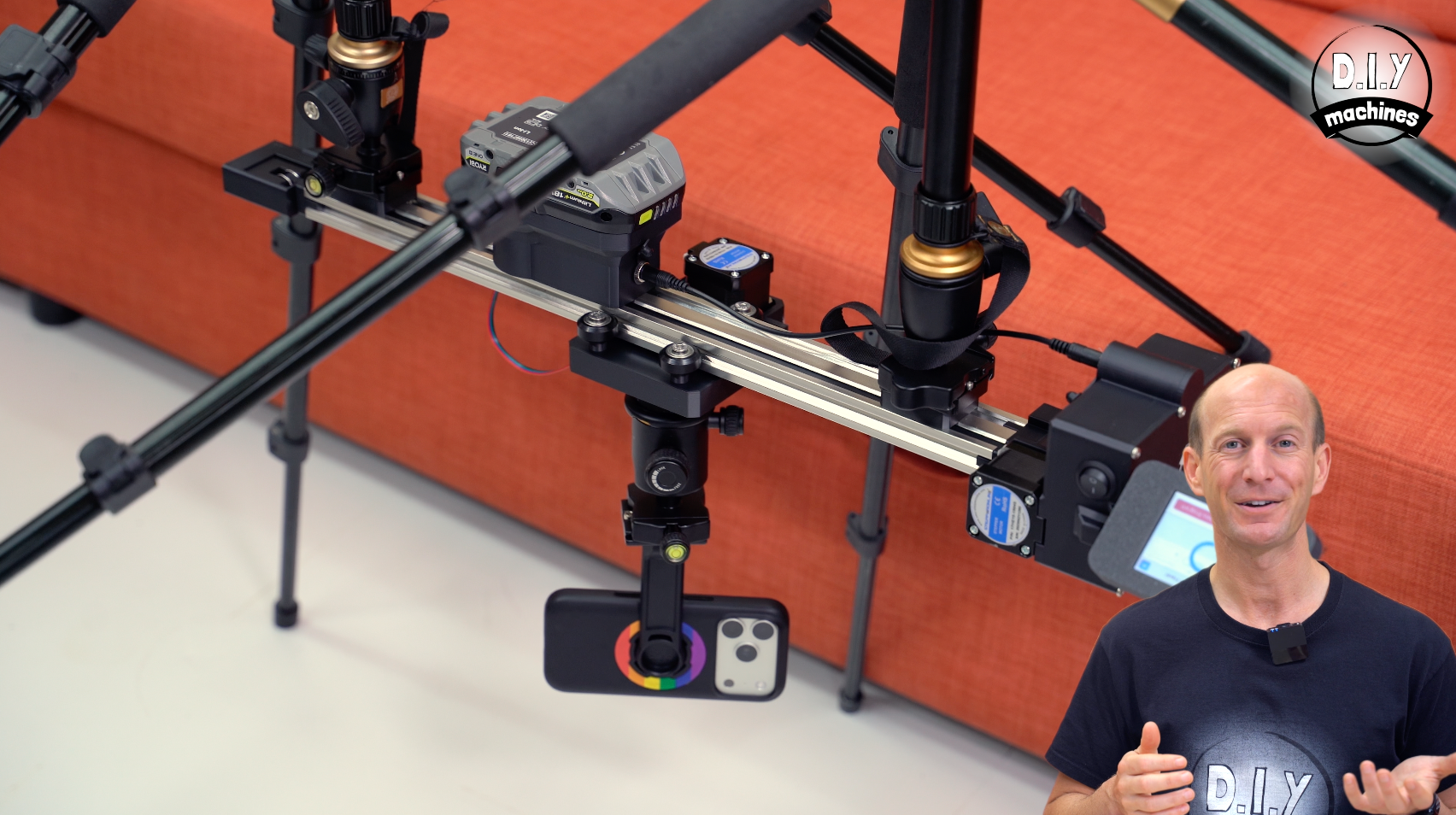
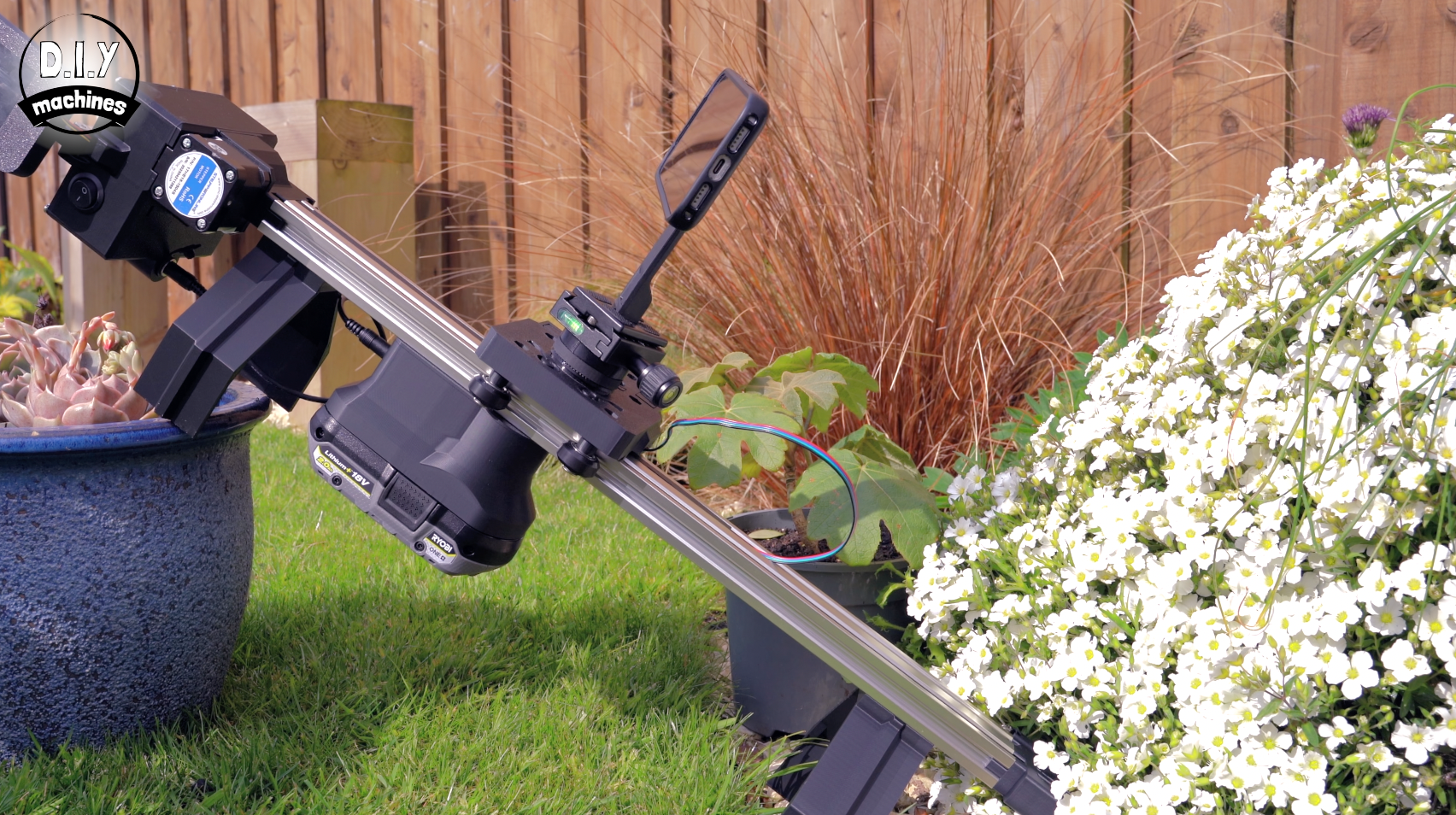
Want smoother camera moves without buying an expensive motorised slider? In this project I’ll show you how I designed and built a 3D printable robotic camera slider with touchscreen control, adjustable track length and support-free printed parts.
It’s designed for live video work, product shots and motion timelapses, with programmable speed, acceleration and movement time. You can build it for tabletop use, tripod mounting, mains power, or with an optional Ryobi battery adaptor for portable filming.
Downloads:
3D models for printing: https://diymachines.etsy.com/listing/4516449862
International shipping Etsy shop (optional kits to help you source components):
www.diymachines.etsy.com (Kit's for this project are still being added)
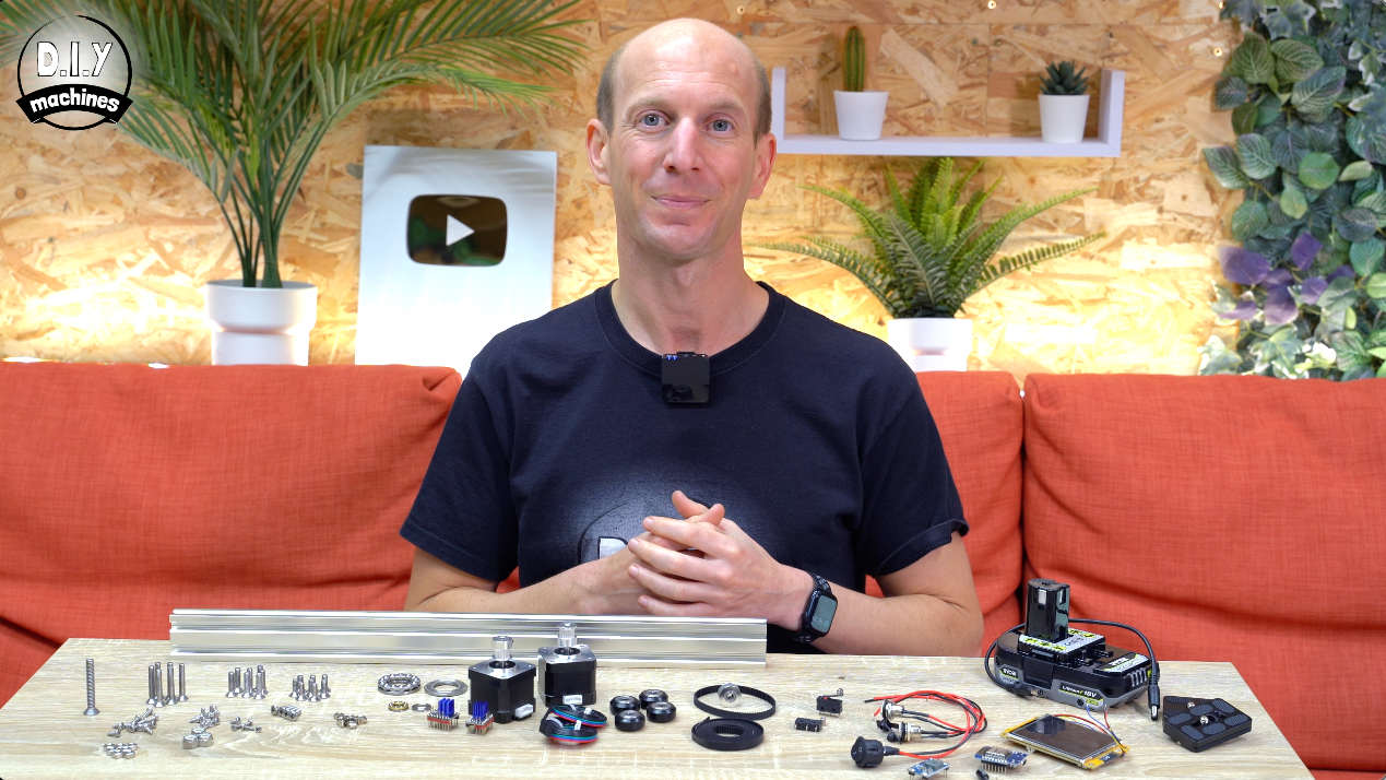
List of items used in this project and where to find them / BOM:
To build one of your own you will need a few items for the relatively simple, but effective, project:
(The links below let you choose between Amazon or AliExpress - As an Amazon Associate I earn from qualifying purchases.)
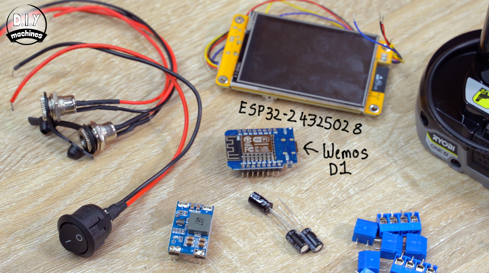
- 2.8" 'Cheap Yellow Display' - ESP32-2432S028 (x1): https://geni.us/CYD-2-8
- Mini560 5v (x1): https://geni.us/Mini560
- TMC2209 Stepper Driver (x2): https://geni.us/TMC2209
- Wemos D1 Mini (ESP8266) (x1): https://geni.us/wemosD1
- Idle GT2 idle wheel (x1): https://geni.us/6mmIdler5mmBoreToothed
- GT2 20T 6mm timing pulley (to go onto stepper motor shafts) 5mm bore (x2): https://geni.us/TimingBelt5m
- Contact Switch (x2): https://geni.us/ContactSwitch
- Panel mountable power switch (x1): https://geni.us/Power-Switch
- Aluminium extrusion 20x40 with both ends M5 threaded(x1) I used a 50cm length: https://geni.us/Extrusion-2040
- Female DC Power Barrel (x2): https://geni.us/FemalePowerBarrel
- 100uf 35v LOW ESR Capacitor (x3): https://geni.us/Capacitor100uF35vESR
- PCB (x1): https://diymachines.etsy.com/uk/listing/4516518337/robotic-camera-slider-pcb-only
- NEMA 17 Stepper Motor (x2): https://geni.us/StepperMotor
- GT2 Timing belt 6mm wide (x1) Need’s to be twice the length of the extrusion plus 25cm: https://geni.us/TimingBelt5m
- POM Pulley 625zz Linear Bearing - 5mm Bore (x4): https://geni.us/625zzBearing-5mm
- 6mm GT2 200mm Circular Belt Loop (x): https://geni.us/GT2BeltLoop-200mm
- Contact Spring - Keystone Electronics 209 (x2): https://geni.us/KeystoneElec209Contact
- Short DC Barrel Lead (x1) or DIY Male connectors (x2): https://geni.us/DCBarrel-MaleToMale
- Optional Ryobi 18v Battery (x1): https://geni.us/Ryobi18v
- Wire: https://geni.us/22AWGWire
- 3D Printing Filament (I used PETG): https://geni.us/3DJake
If you want to screw your wires to the PCB instead of solder them on directly:
- Screw Wire Terminal - Through Hole Mount - 4 Pole (x3): https://geni.us/PCBScrewTerminals
- Screw Wire Terminal - Through Hole Mount - 2 Pole (x5): https://geni.us/PCBScrewTerminals
Nuts, Bolts, and bearings you'll need:
You can buy a kit of the below nut, bolts and bearings on Etsy for convenience: (a link will be provided shortly)
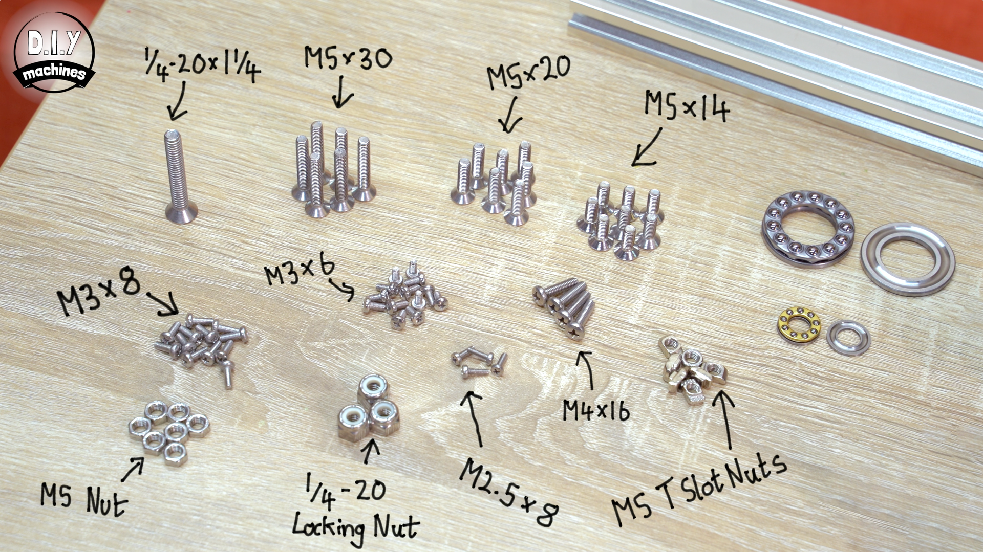
- 1/4-20 Locking Nut (x3)
- 1/4-20x1.3/4 Machine Screw (x1)
- M2.5x8mm (x4):
- M5 x 30 Countersunk Bolt (x6)
- M5x20 Countersunk Bolt (x7)
- M5x14 Countersunk Bolt (x8)
- M3x6 (x13):
- M3x8 Bolt (x12)
- M5 Nut (x8)
- ‘Drop In’ M5 T Slot Nuts (x6):
- F8-16M 8X16X5mm Axial Ball Bearing (x1)
- Thrust Ball Bearings 20mm x 35mm x 10mm (x1): https://geni.us/ThrustBearing-51104
To attach you slider to tripod's using a universal quick release plate:
- Optional - Photography Quick Release Pate (One or Two): https://geni.us/PhotoQuickReleasePlate
For the optional fan to cool the electronics (needed in hot environment or for fast movements for long periods of time):
- 5v 40mm fan (x1 optional): https://geni.us/40mmFan
- M4x16 Bolts to mount optional fan (x4)
Wiring Diagram
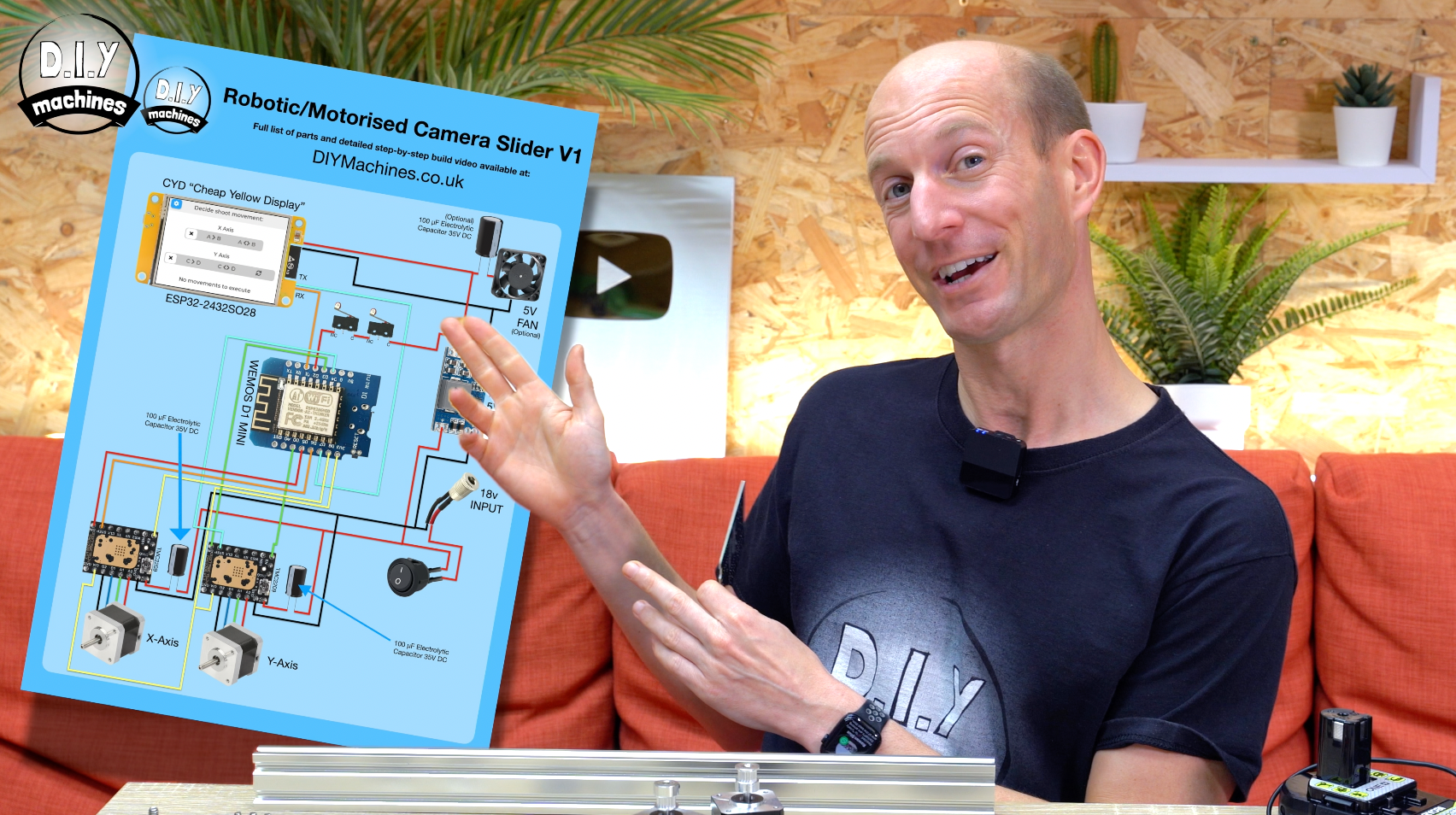
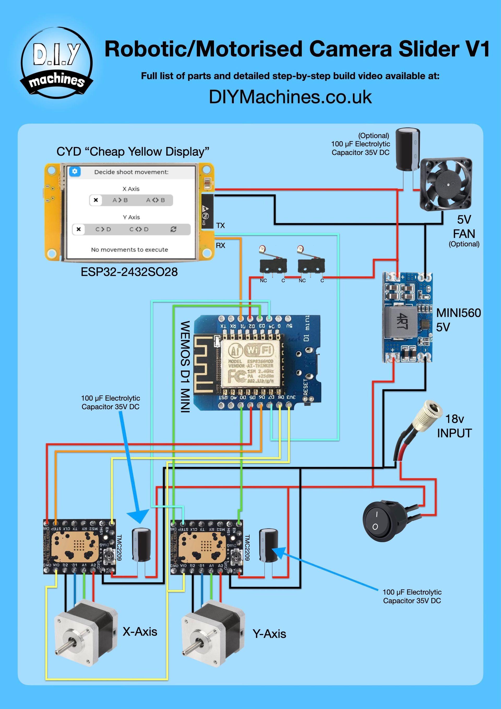
If you would like to assemble your own circuit instead of using the PCB I have designed then I have created a graphical wiring diagram you can find below o to help you understand the electronics:
How to Build your Robotic Camera Slider
Full written instructions are on the way (it takes me a few evening to write it all out). They will be done by the end of June 2026. All the information to build your own can be find in my two detailed videos at the top of this page for now. :)
I have created a series of two videos which show in detail how to build one of your own photographic sliders You'll find both at the top of this page. I've also written out all the same amount of information without skipping any details below - so feel free to use the video or written instructions (or both!) to help you build your own along with me.
If you're going to follow this written guide, then I do encourage you to watch the first two/three minutes of the first video to see how the slider works and the features you'll have on yours once it's complete.
What you'll need / BOM
I have created and listed a detail inventory of all the hardware and electronics you'll ned to create your own slider.
It's listed under the section 'BOM' further up the page (below the videos).
There are links provided to both Amazon and AliExpress for most items as well as SteppersOnline for the stepper motors I used.
Wiring Diagram and PCB Options
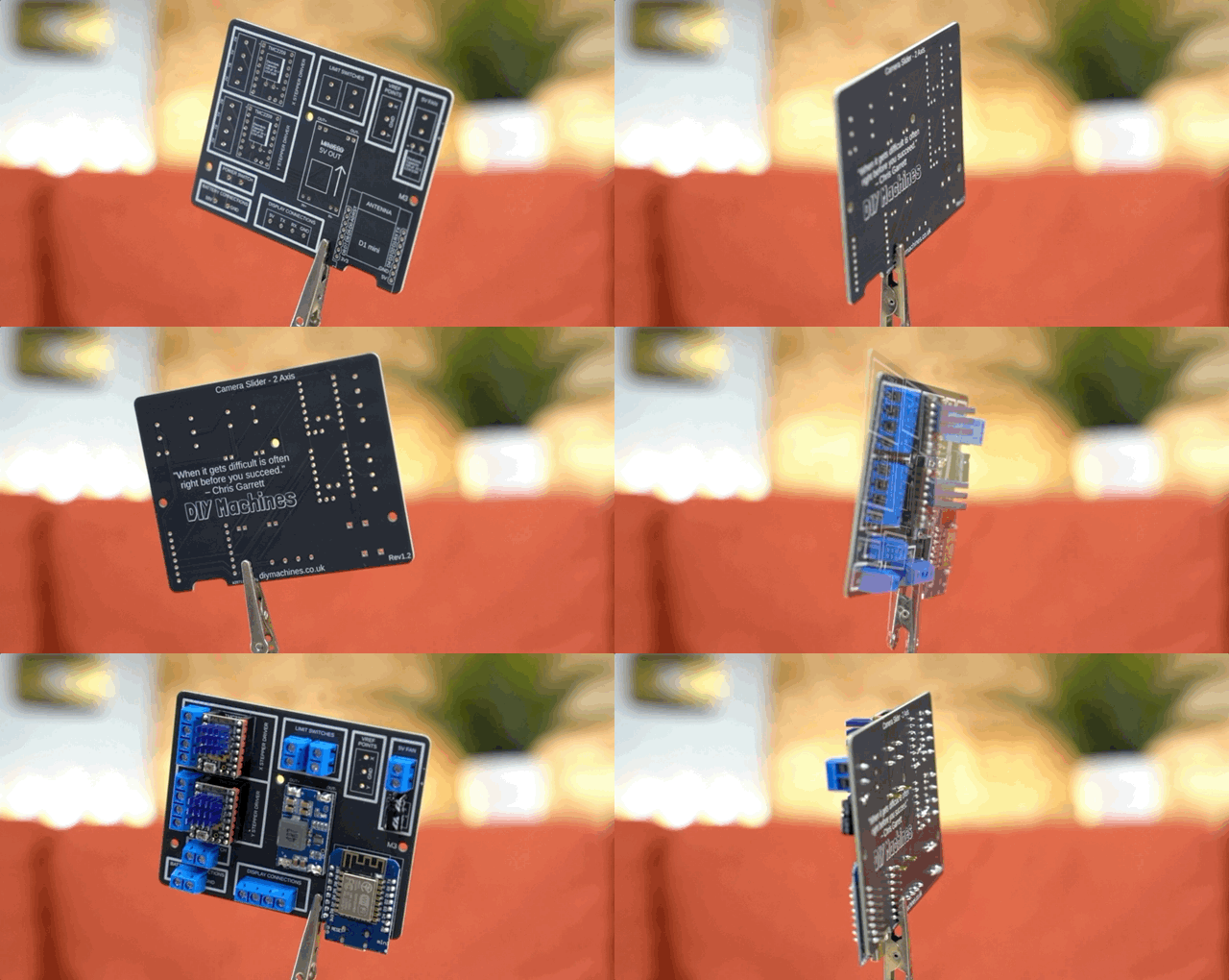
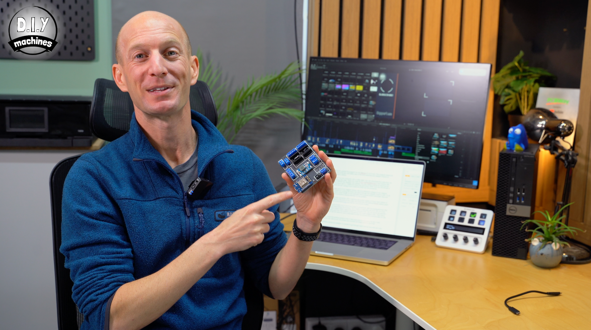
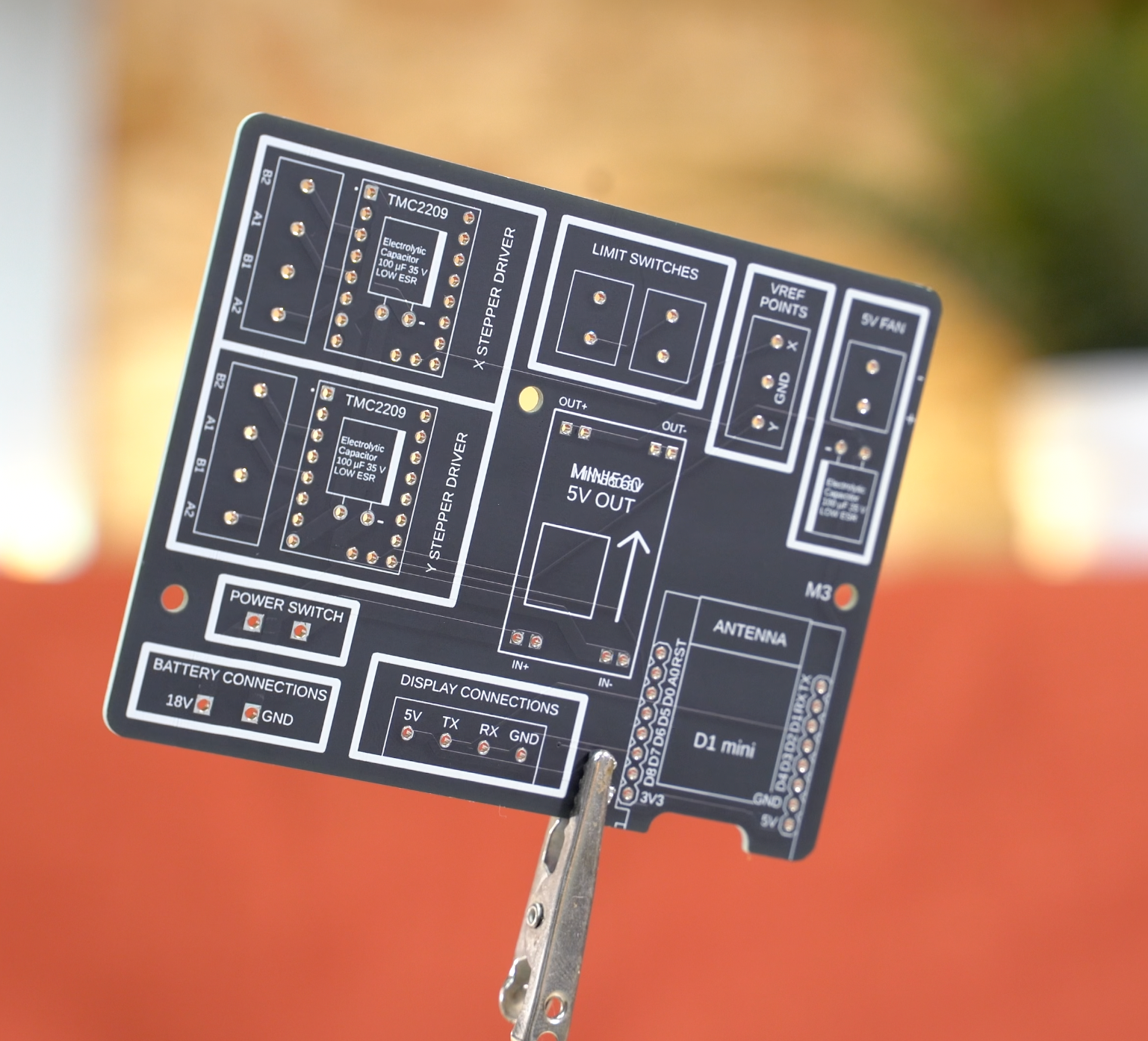
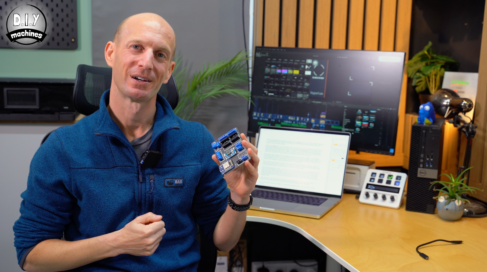
I have also designed a Custom PCB for this project which vastly simplifies the wiring, I’ll show you how to assemble it as we go through the project together. I highly recommend it.
There is also a graphical wiring diagram I created if you wanted to build out your own circuit. It’s included further above this page in the section 'Wiring Diagram'.
Our First 3D Prints
You’ll first need to print the ‘Camera Platform’, ‘Small Bearing Case’ and ‘Large Bearing Mount’.
I have also worked hard so that all of the parts in this project can be 3D printed without the need for any supports. This saves time, cost, and reduces the environmental impact of waste plastic.
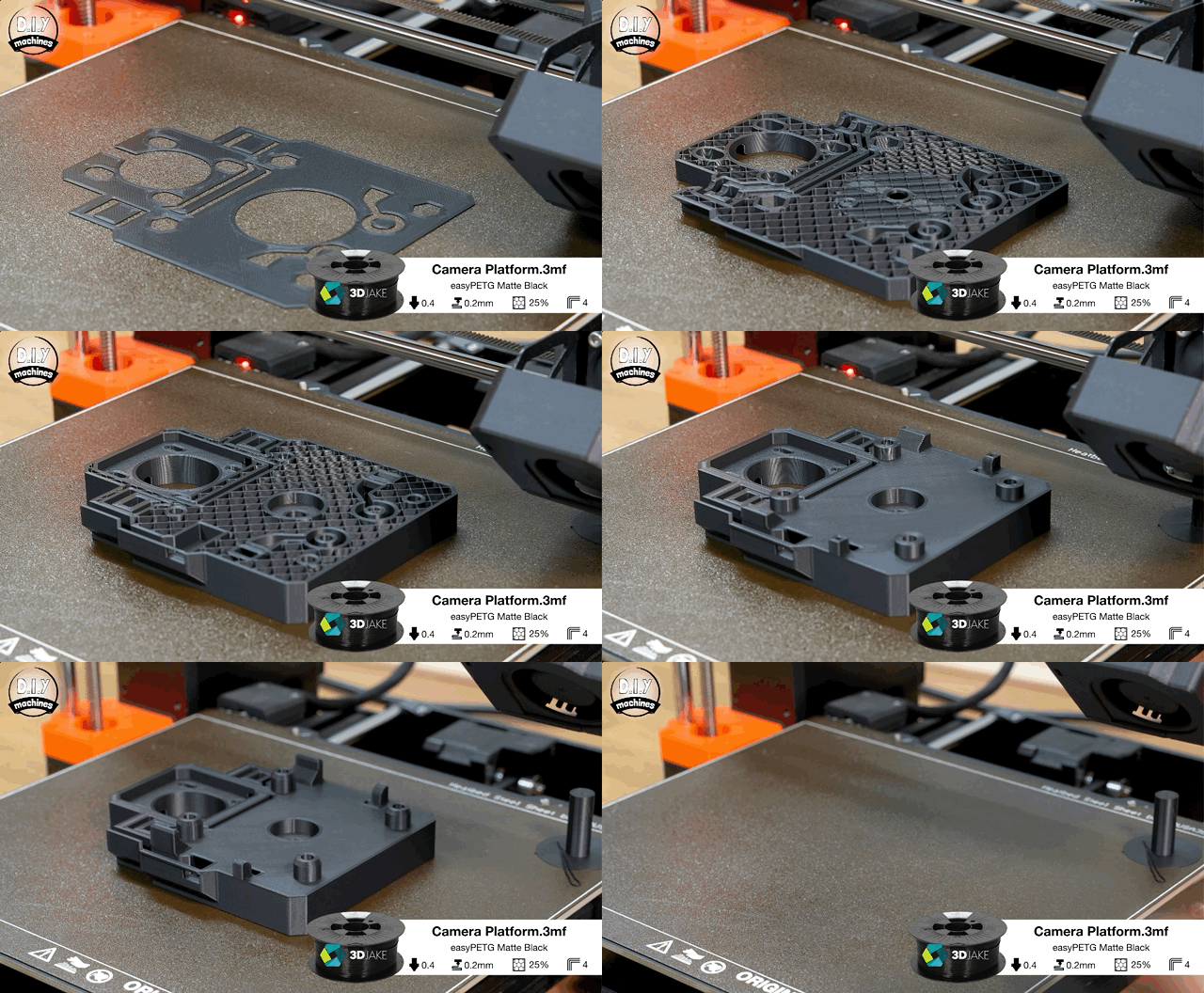
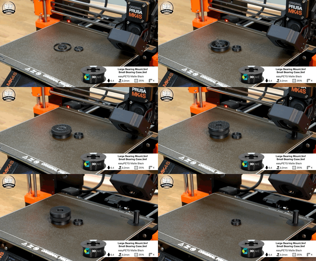
All the 3D prints required for this project can be downloaded here: https://www.etsy.com/listing/4516449862/robotic-camera-slider-3d-printable-files
As the 3D printed parts in this project are mechanical in nature It is recommend to increase the number of perimeters to at least 4 walls and the infill to 20% or higher. I used PETG for my parts in a matt black colour.
Assembling the Platforms Bearings
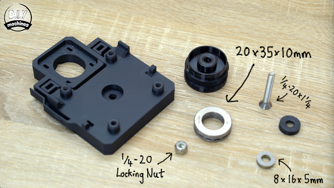
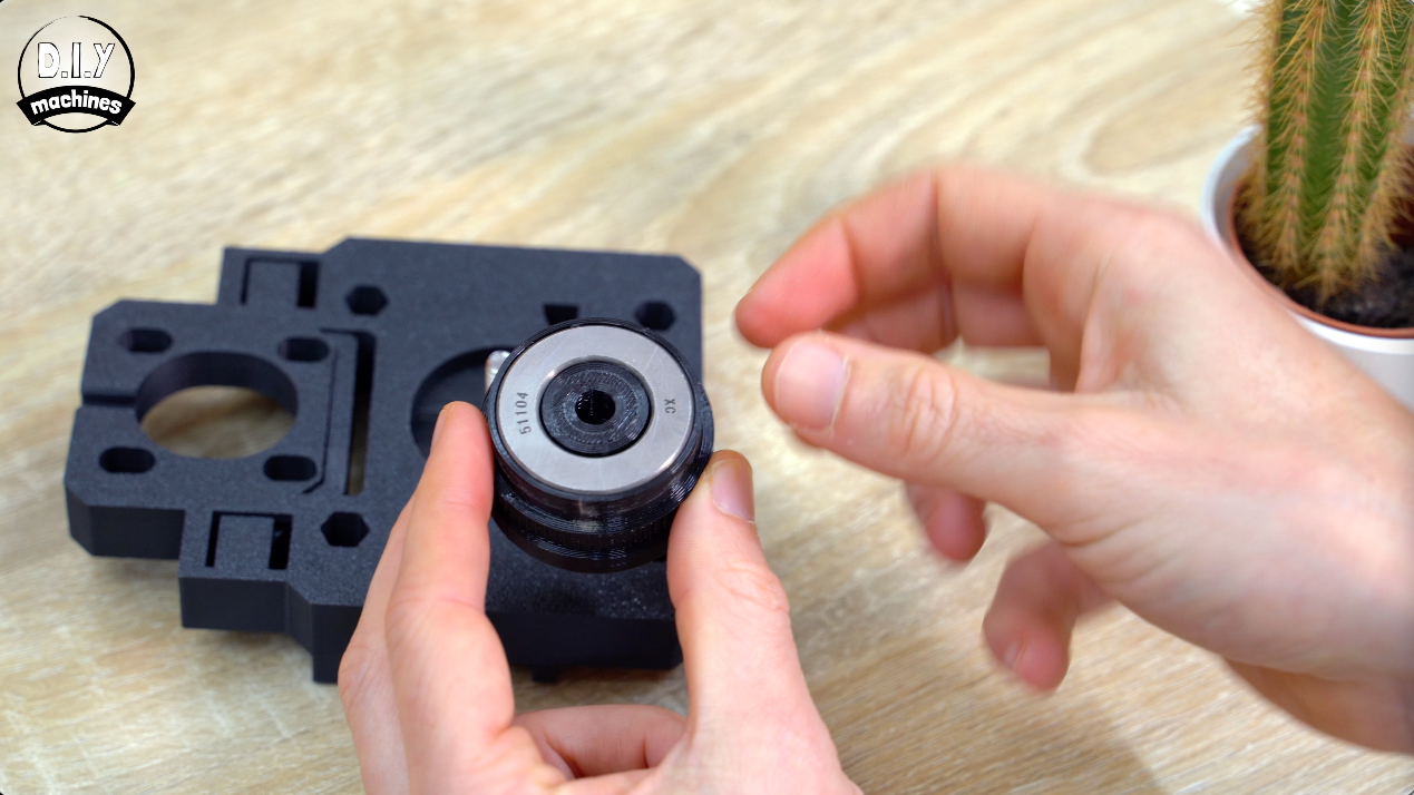
Put your small bearing inside the 3d Printed case then pass the 1/4-20 bolt through both parts.
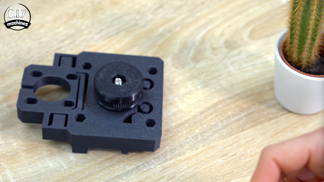
This is then passed through the base of the platform. Now pop the large bearing inside the large bearing mount and thread the bolt through this assembly as well.
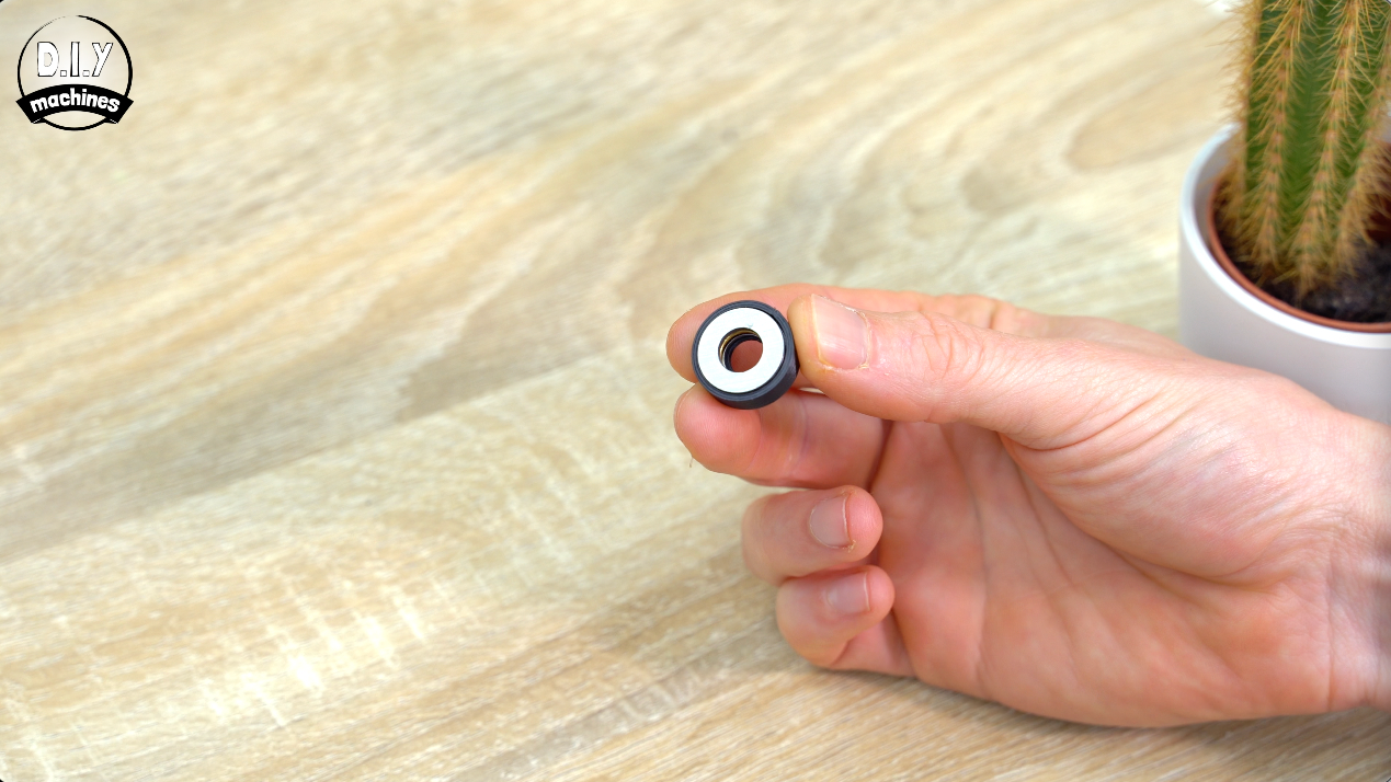
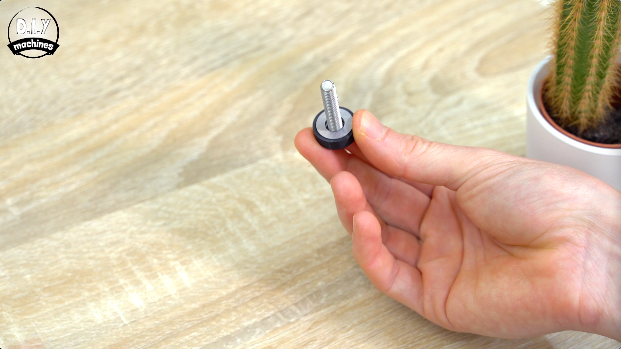
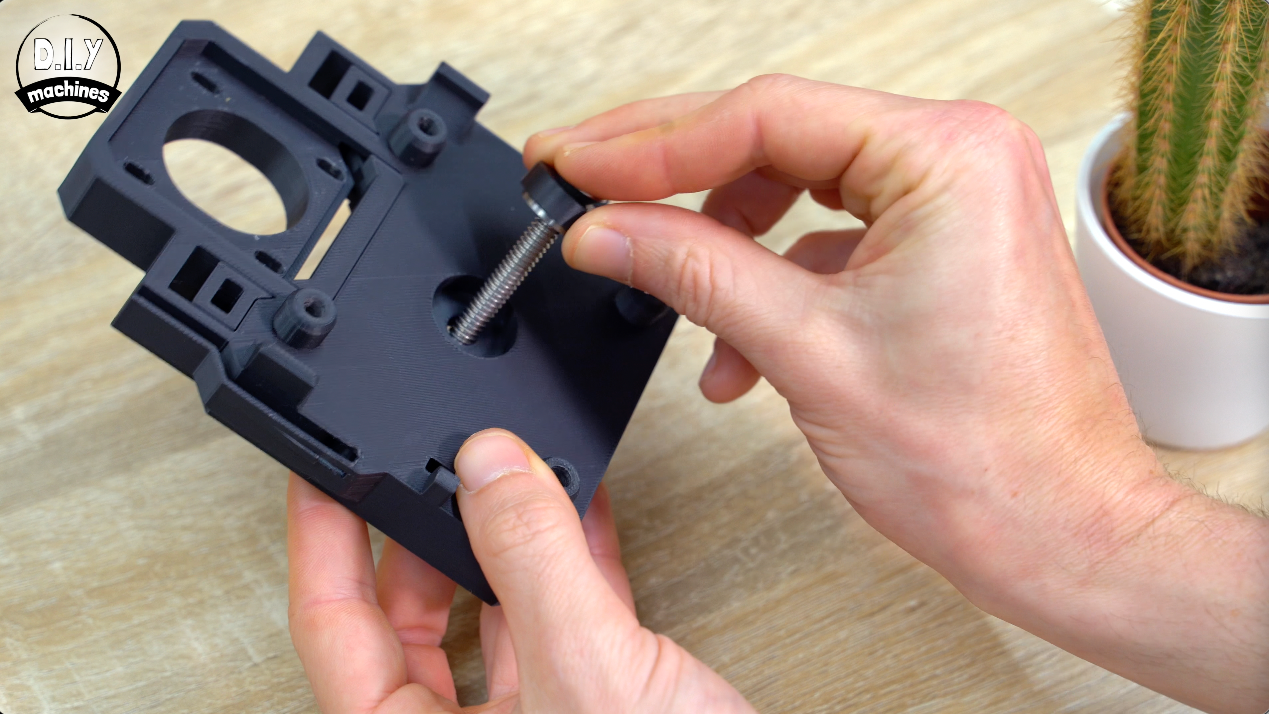
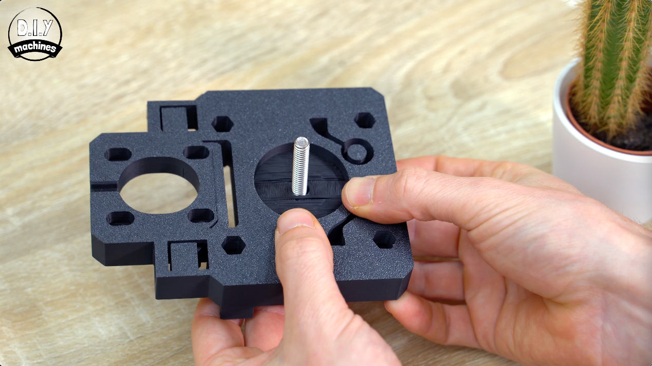
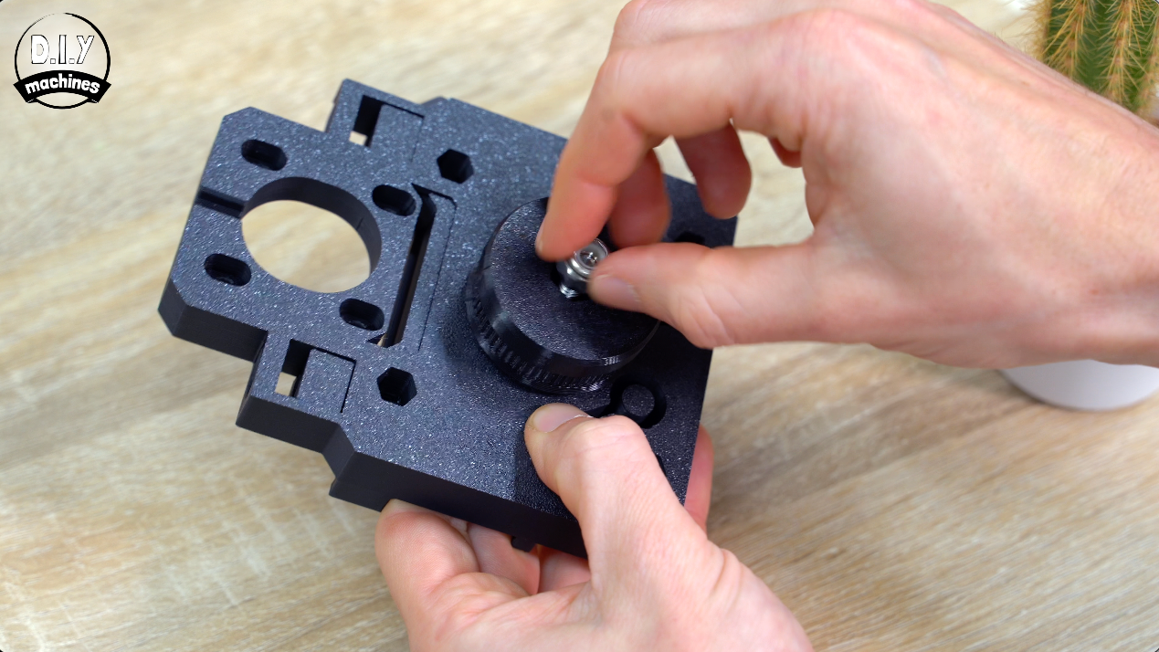
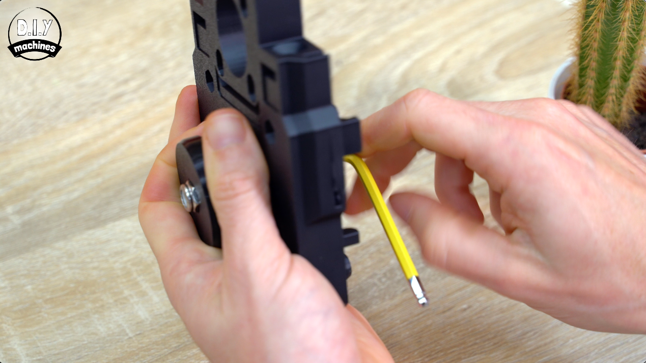
The locking nut is added by hand until it fit’s into the hexagonal recess in the print. We can then use an Allen key to tighten this fully before slightly loosening it so that we can rotate the large teethed wheel on top the platform without it wobbling.
Preparing Y Axis 'Brace'
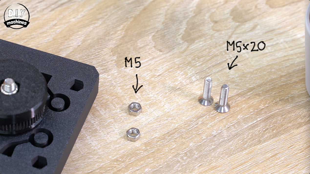
Next we’ll add the Y axis motor - that’s the one which will be able to spin a camera around.
To prepare for this we need to start by inserting a M5 nut into each of the recesses on the underside of the platform and use an Allen key or similar to align it with the bolt hole when viewed through the ends.
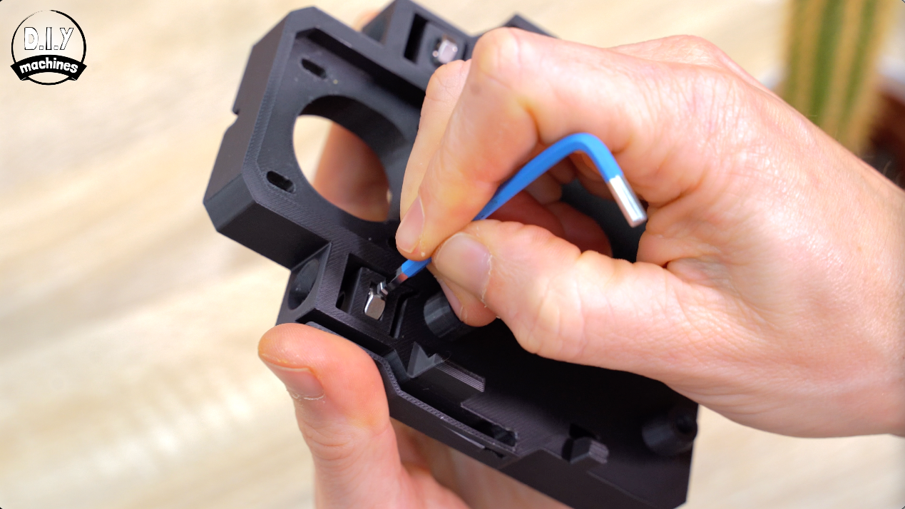
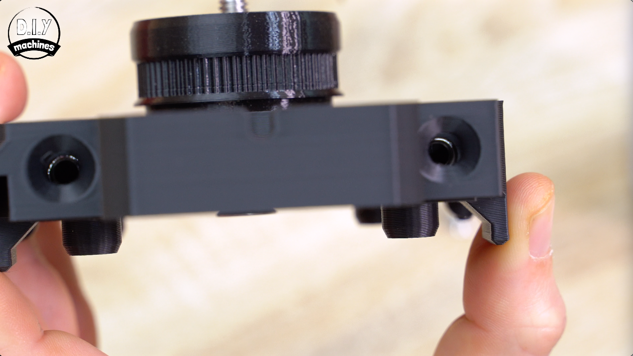
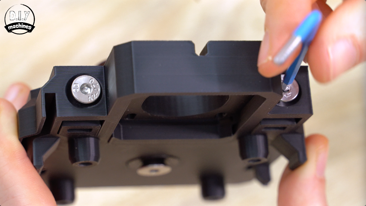
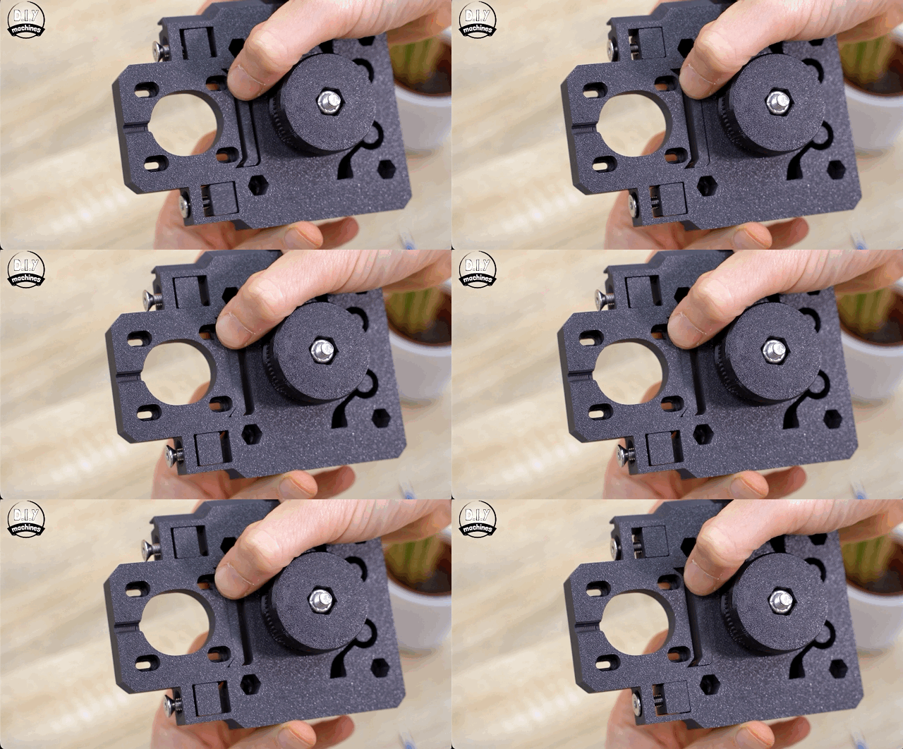
Then add an M5x20 bolt to each until they begin to grab the nut - do not tighten them any further yet as we want this motor positing part to be move freely for now.
We’ll use these bolts to adjust the tension on the timing belt shortly.
Installing the Y Axis Stepper Motor
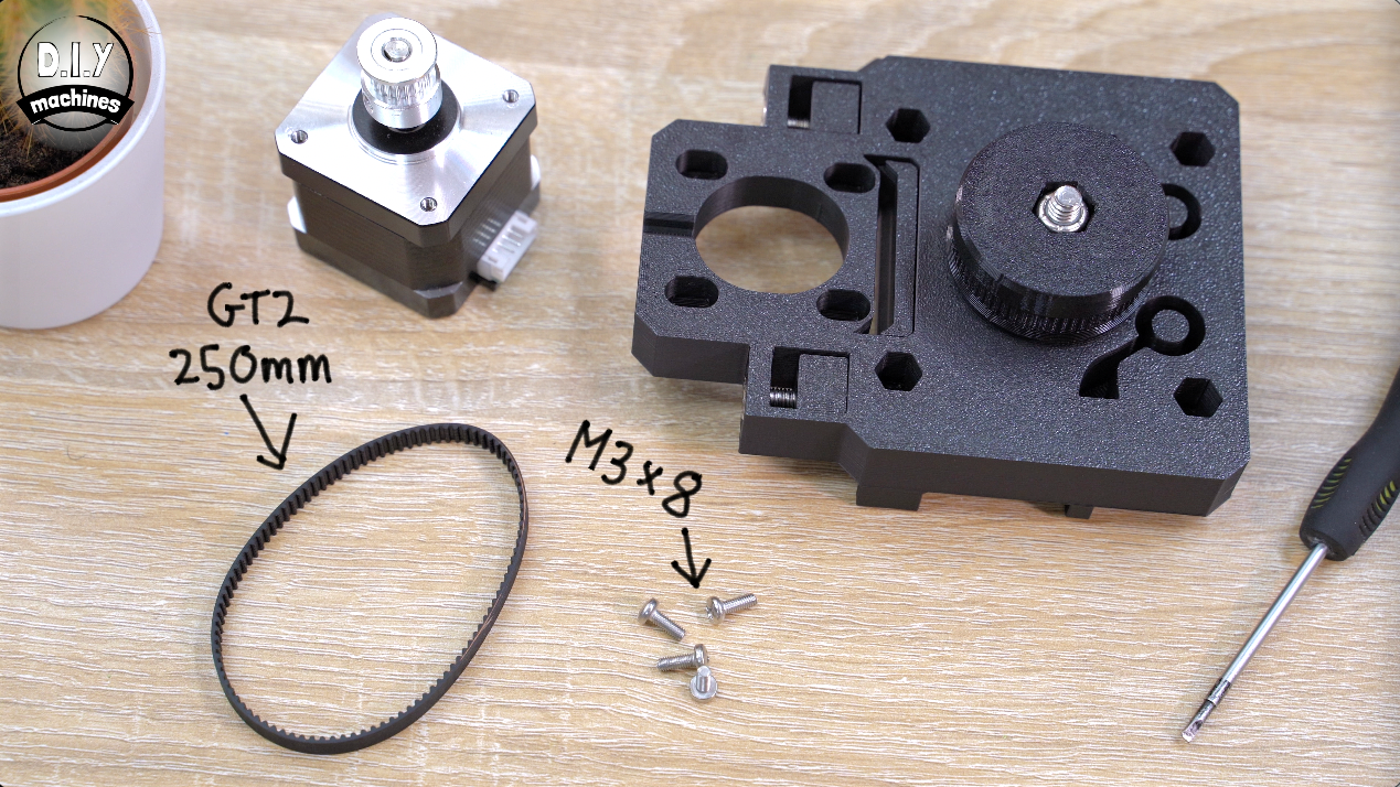
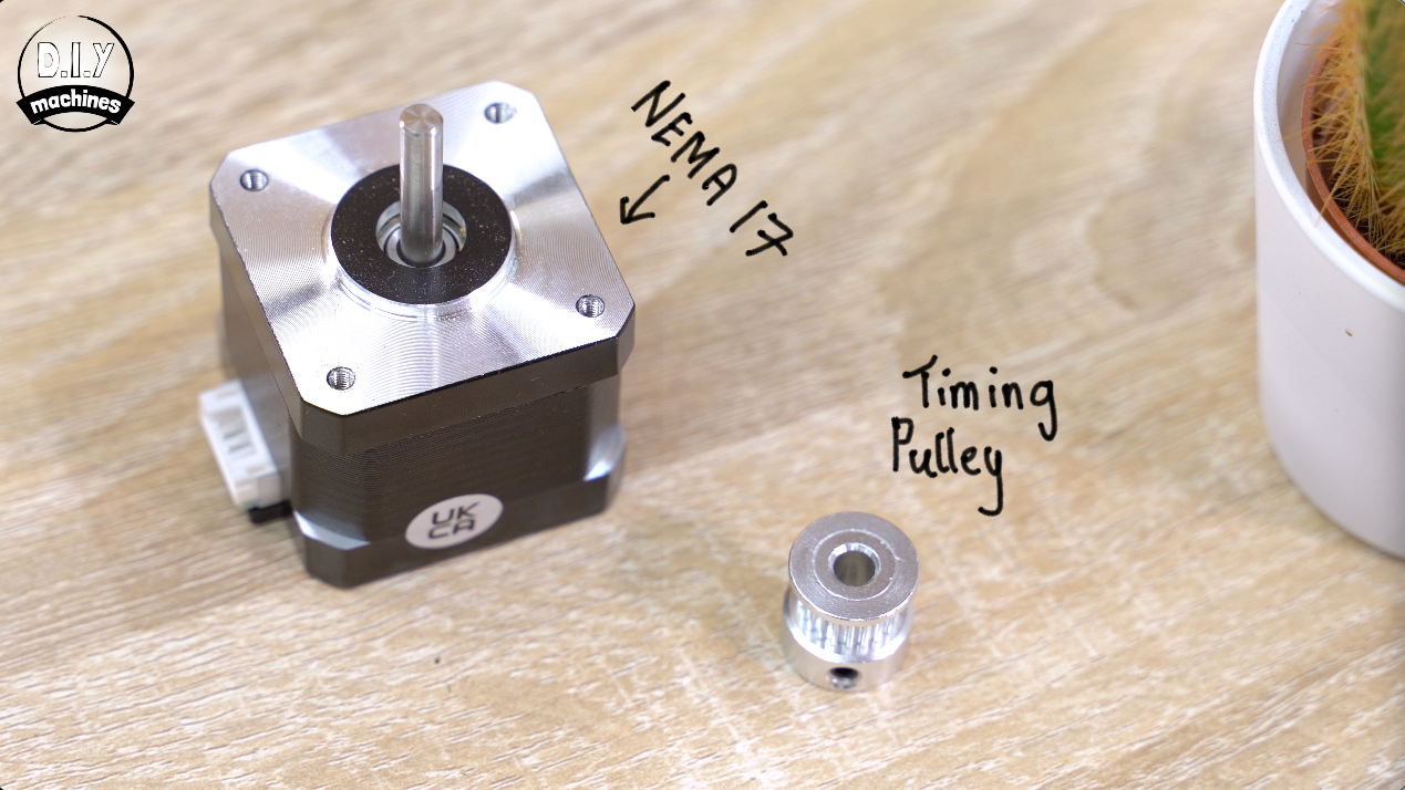
The teethed pulley can be added to the shaft of the stepper motor.
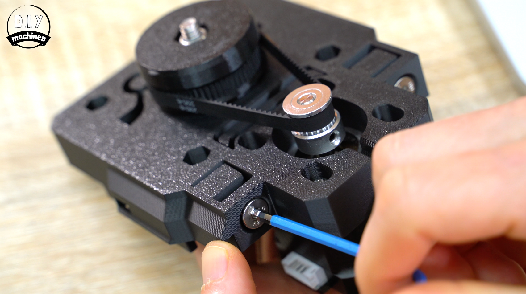
Slide it over the end with the teethed end towards the top. Align it flat with the end of the shaft and then tighten the grub screw ensuring that at least one of the grub screws tightens against the flat edge of the shaft. This provides it with proper grip.
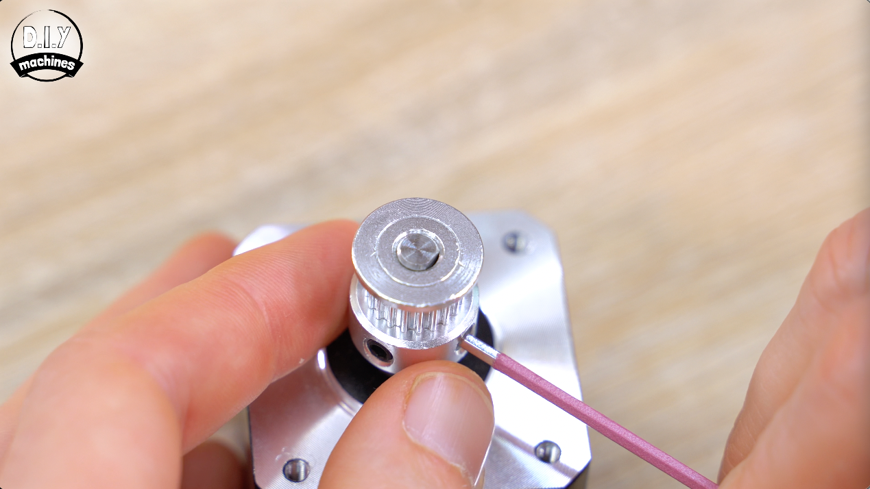
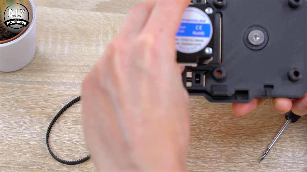
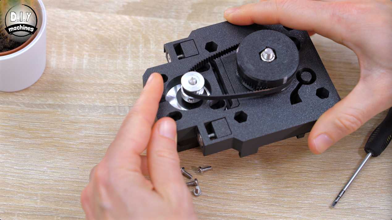
We can now attach the stepper motor to the 3D printed camera platform. When doing this you need to have its electrical connector face the same side as the channel the wires will run through later (see the photos).
Slide the 25cm long GT2 belt over the two pulleys and use four M3x8 bolts to attach the motor Keep these loose as well for now.
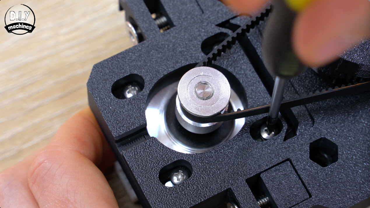
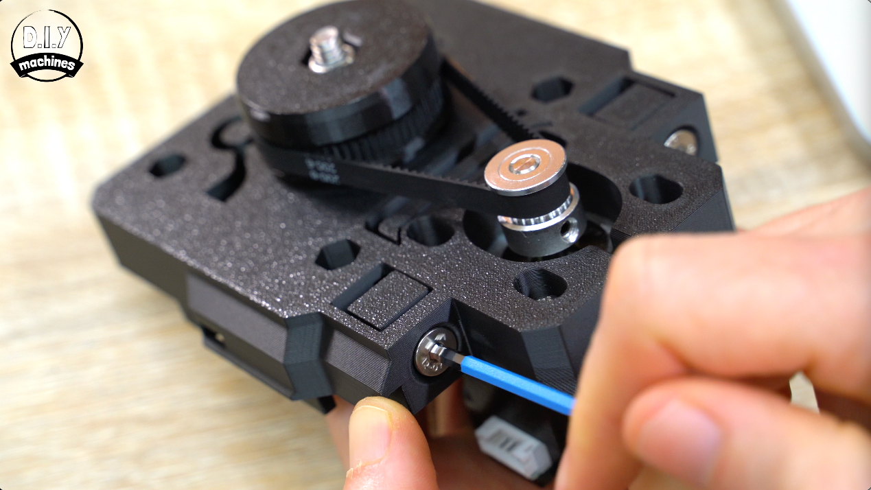
By the way, if you need to adjust the grubs screws later, you can still access them through the little notch in the 3D print I added for your convenience.
The belt is likely to be a little too slack at the moment, so now we can gently tighten the two side bolts to pull the motor away to increase the tension of the belt. We don’t want it to be super taut, just enough that when we turn the small pulley by hand a step in each direction we see the large pulley react immediately when we change direction.
Don’t worry, you can adjust this easily later when you start using your slider. For now we can tighten the four M3 screws attaching the stepper motor to hold it in this position.
Routing The Y Axis Motor Cable
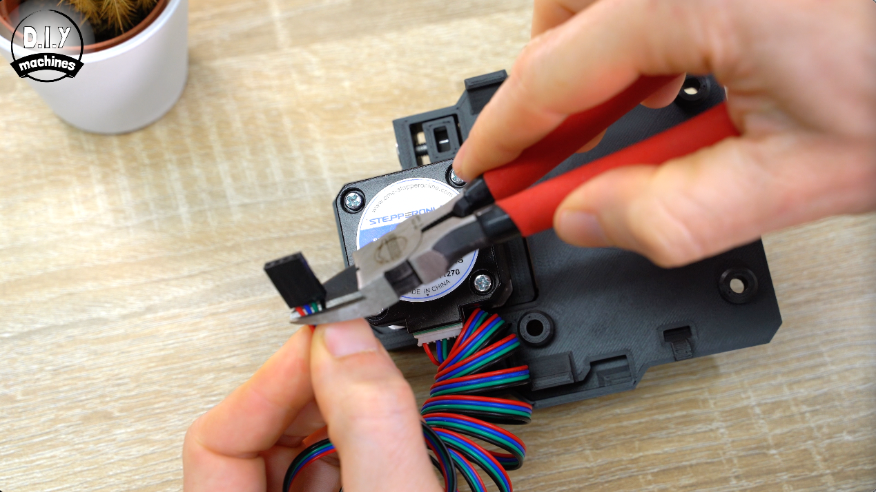
Plug your steppers power cable into the stepper and then trim off the connector at the other end of the cable.
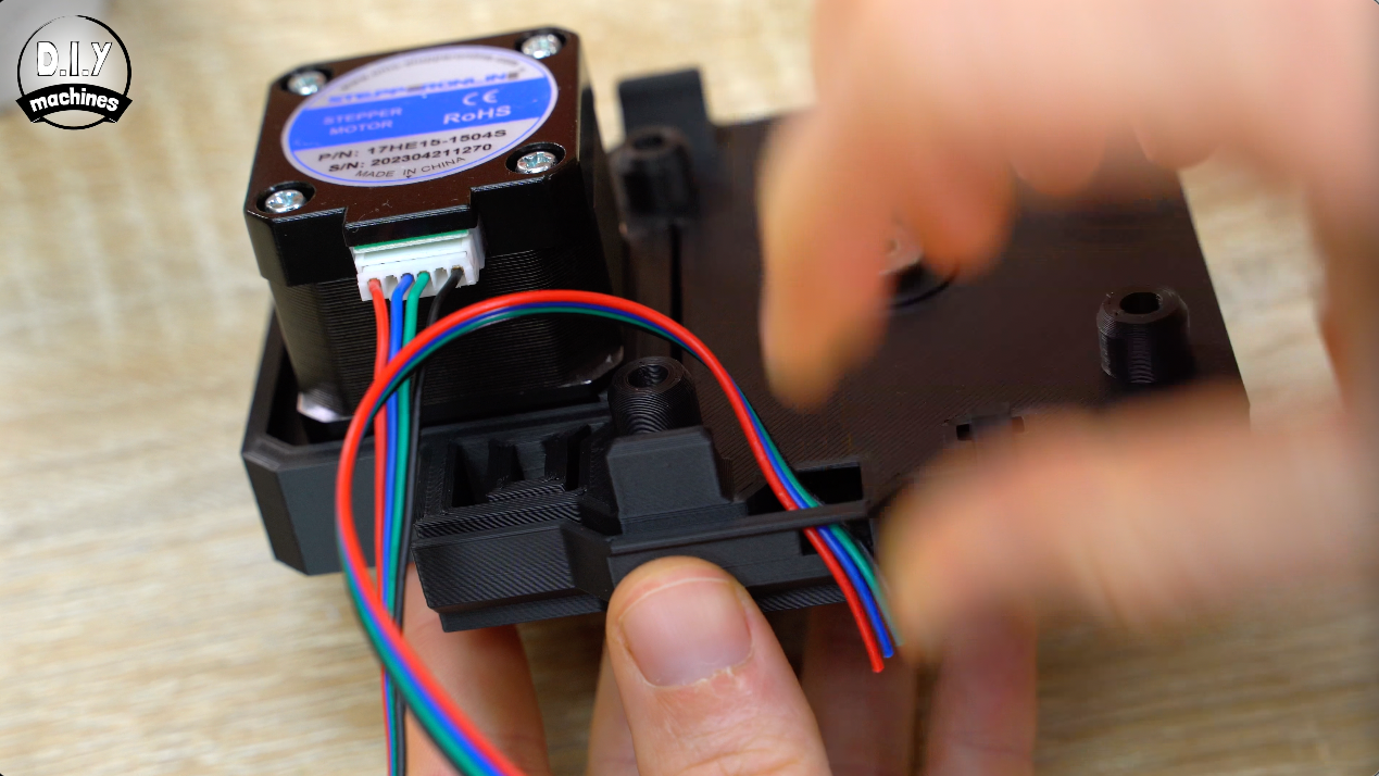
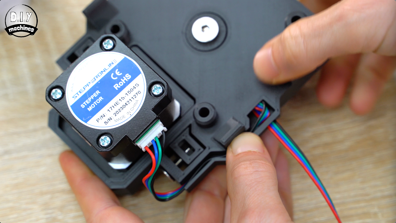
We route this through the channel, then turn it 90º and out through the slot.
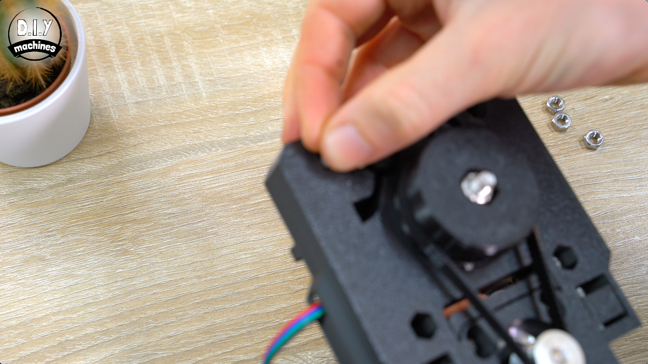
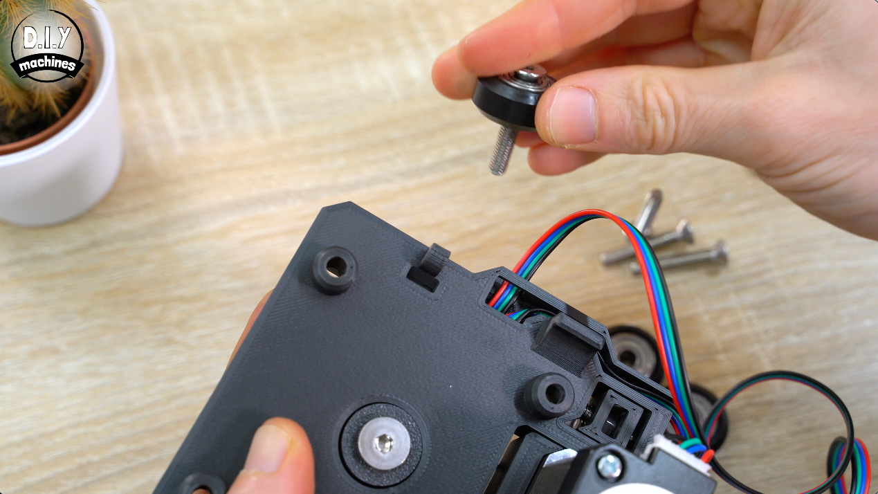
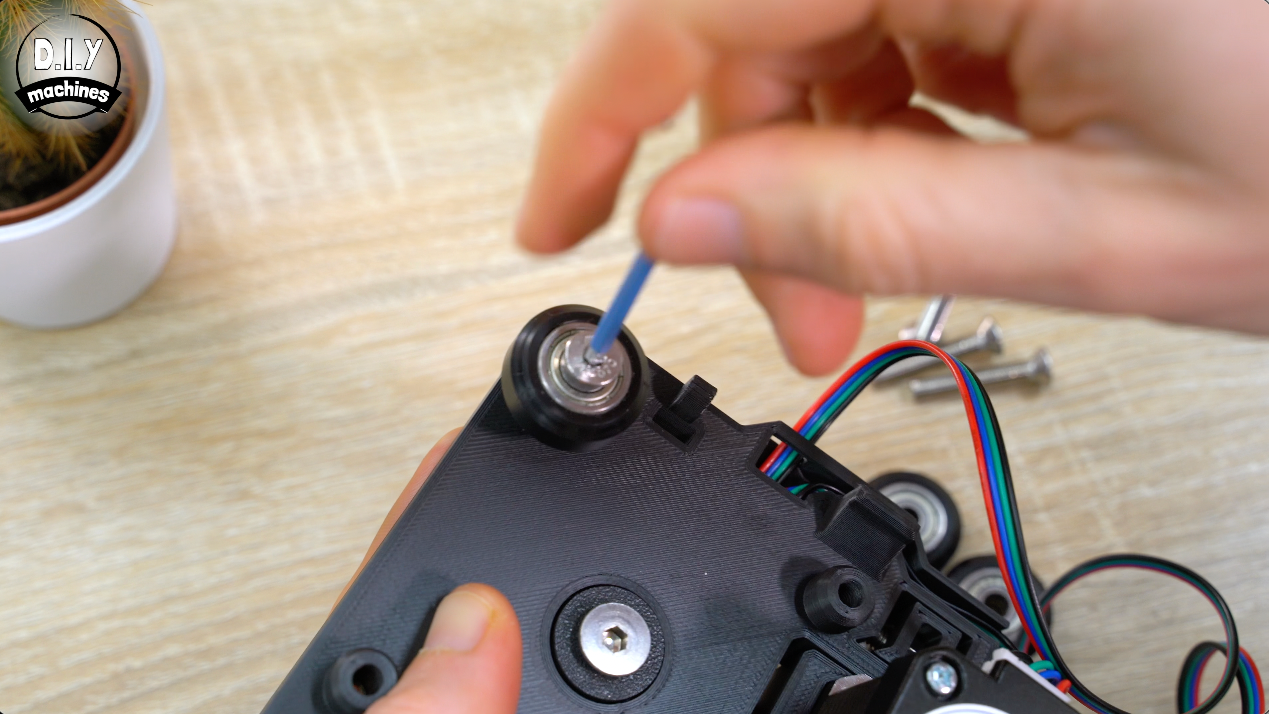
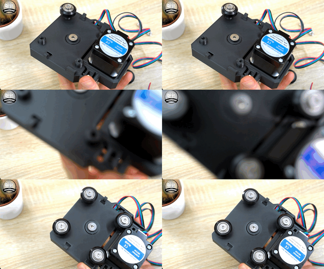
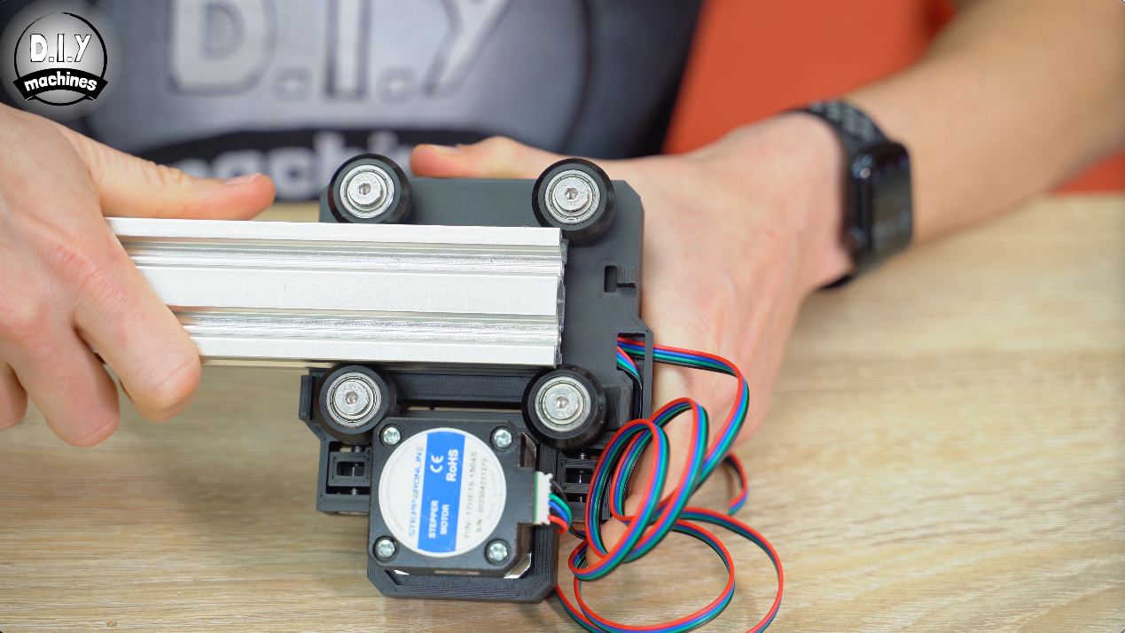
Adding the Wheels
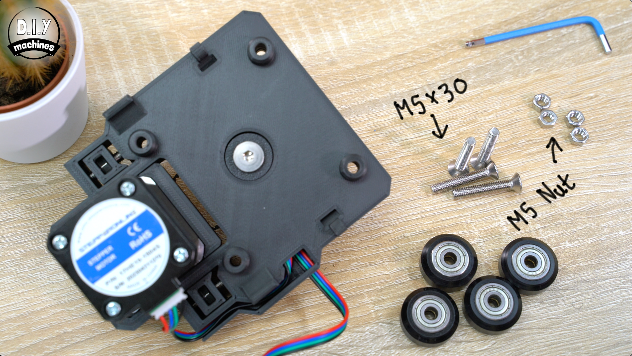
Plug your steppers power cable into the stepper and then trim off the connector at the other end of the cable.
We route this through the channel, then turn it 90º and out through the slot.
Test the Camera Platforms Mounting Hardware
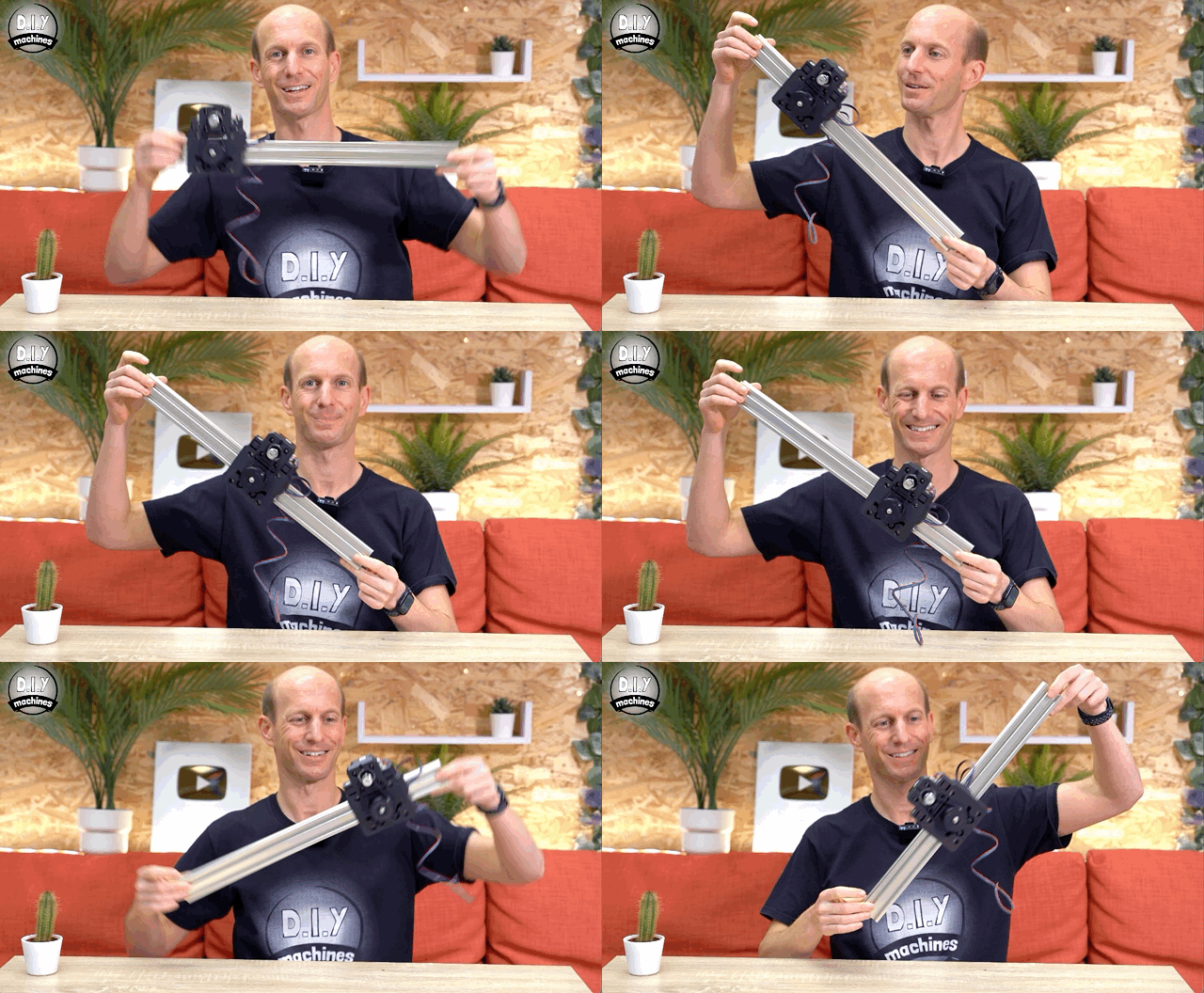
At this point you can go ahead and try it on your length of aluminium extrusion. :) Top tip, it should move very quietly, if you’re does not then check the bolt going through the bearings is not rubbing - if it is you may need to tighten it slightly.
Adding a Contact Switch to the 'Idle' End
You’ll need to print both the “X Axis Idle End” and “Idler Wheel Mount” for the next few steps.
By the way, this awesome motion timelapse below was filmed using this very same slider! Cool isn't it!
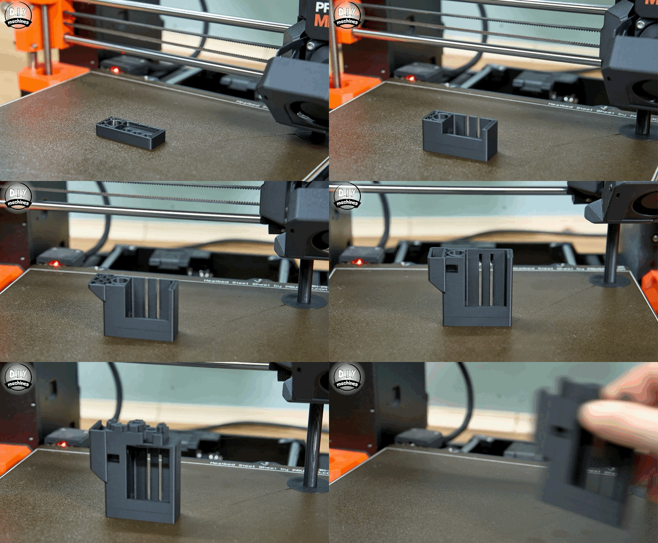
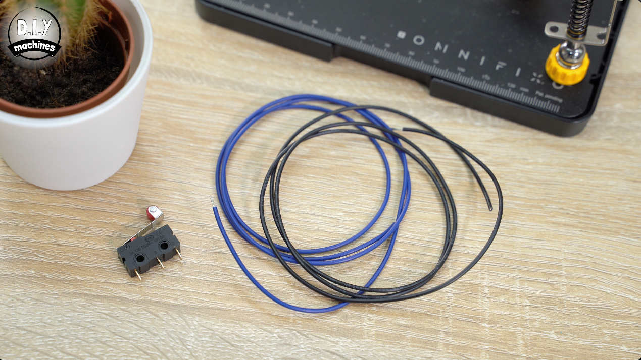
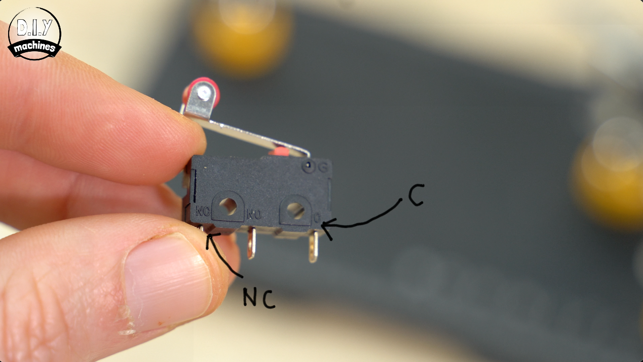
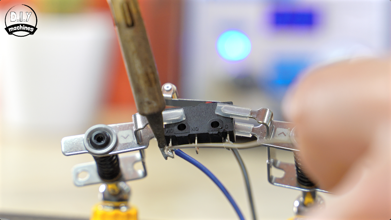
While they print we can solder a pair of wires to one of your contact switches Normally Closed (NC) and Common (C) legs.
This means we will see a completed circuit until the switch is pressed by the camera's platform. This will break the circuit and we know to stop the motion in the current direction. This is a 'fail-safe' way of configuring it as if a wire/connection is broken on the contact switches circuit it will also cause the slider to stop.
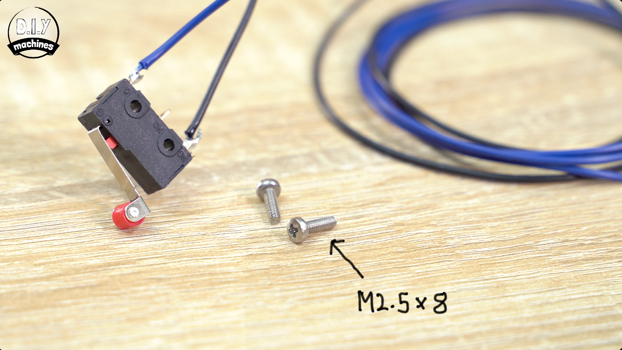
The wire needs to be the length of the extrusion plus 20cm.
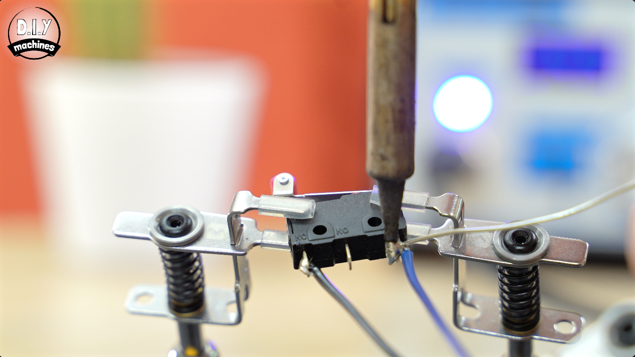
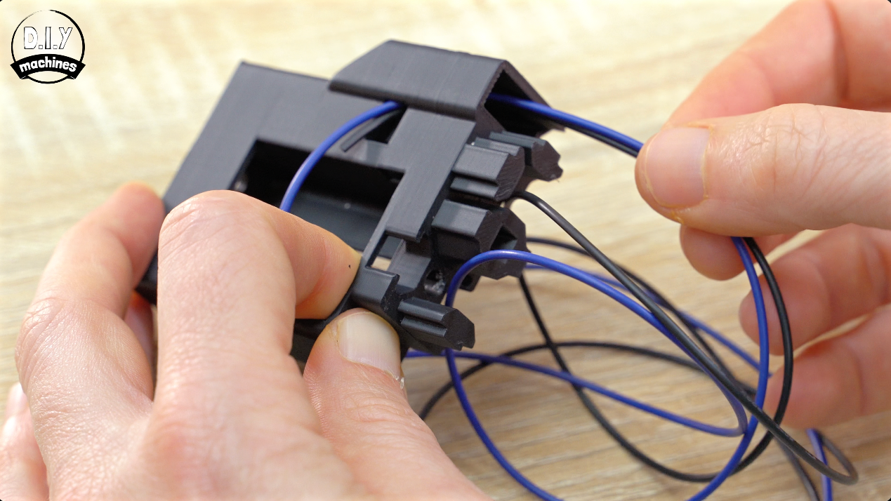
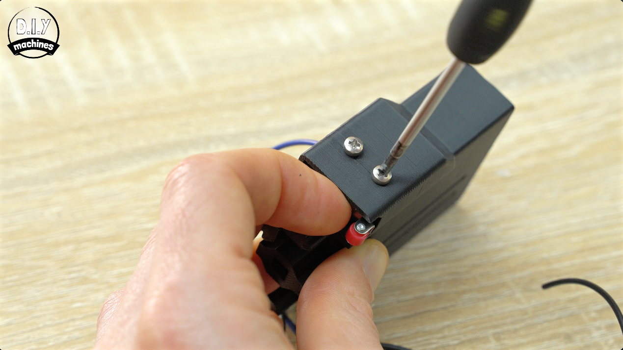
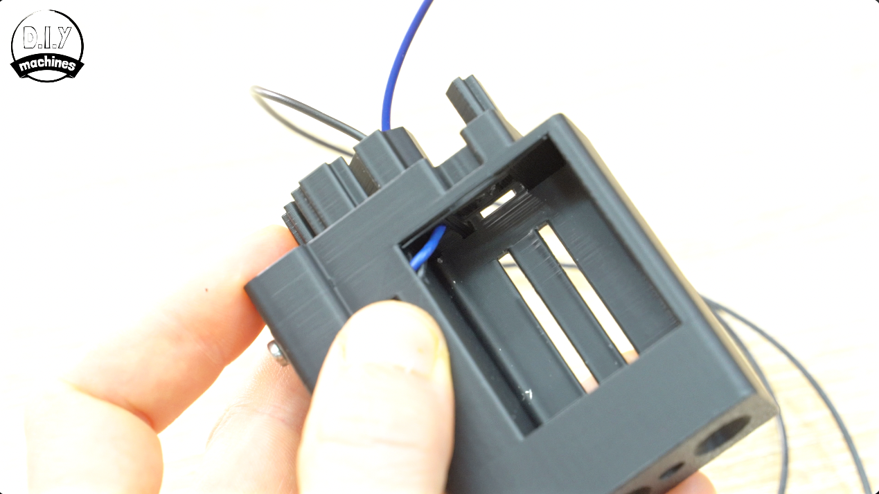
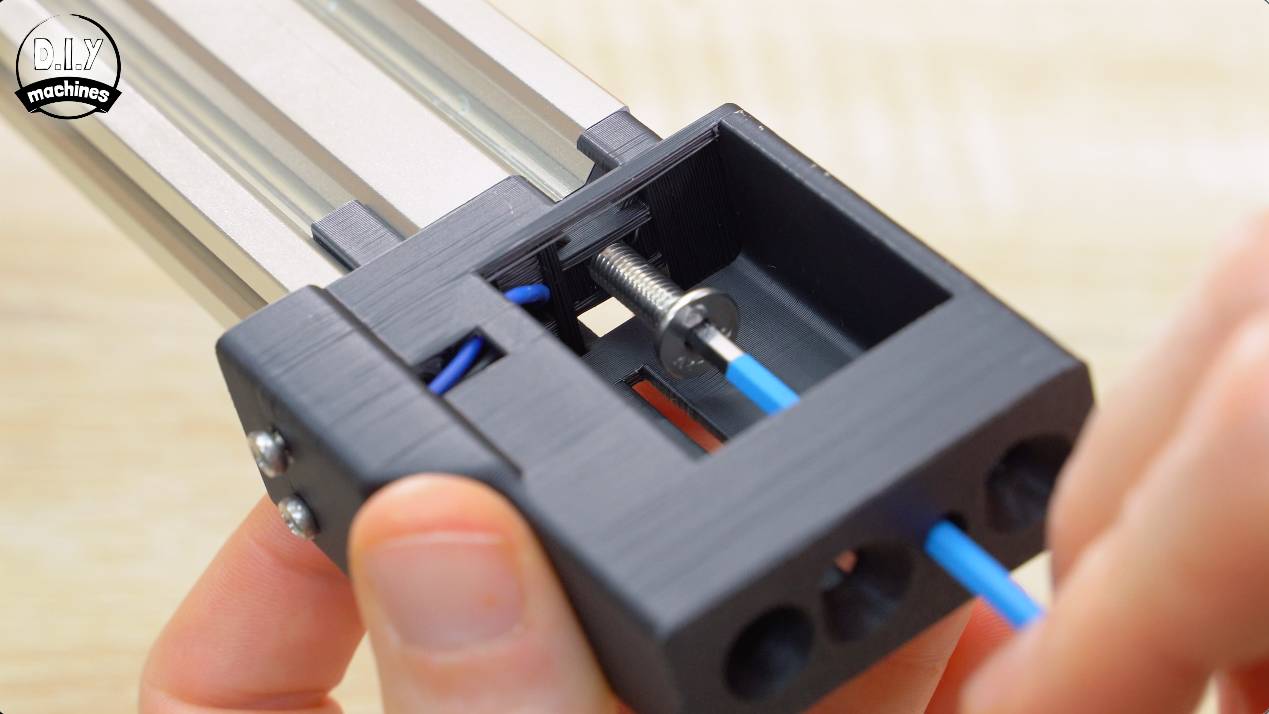
Feed this into the switch housing guiding around the internal path as shown. Pull it through and fit the contact switch with two of your M2.5x8mm bolts.
Continue feeding the wires though the final bit of the pathways central hole as shown in the photos.
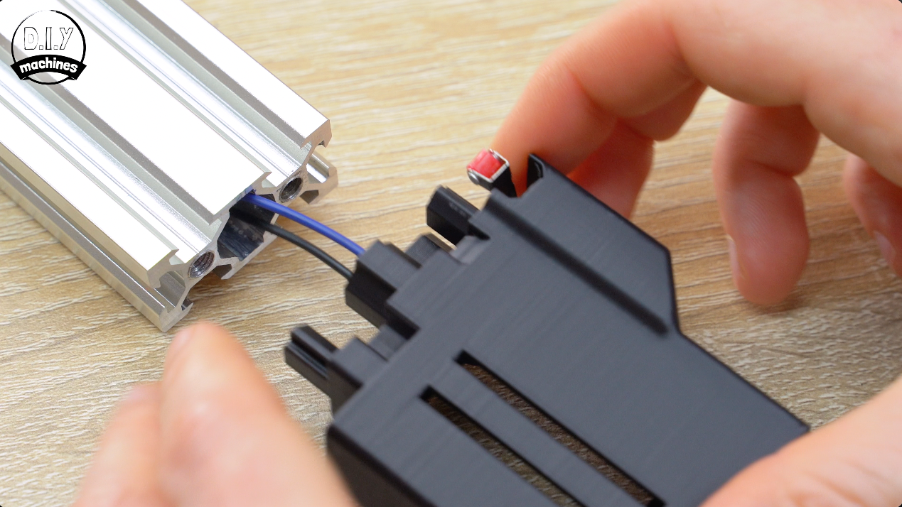
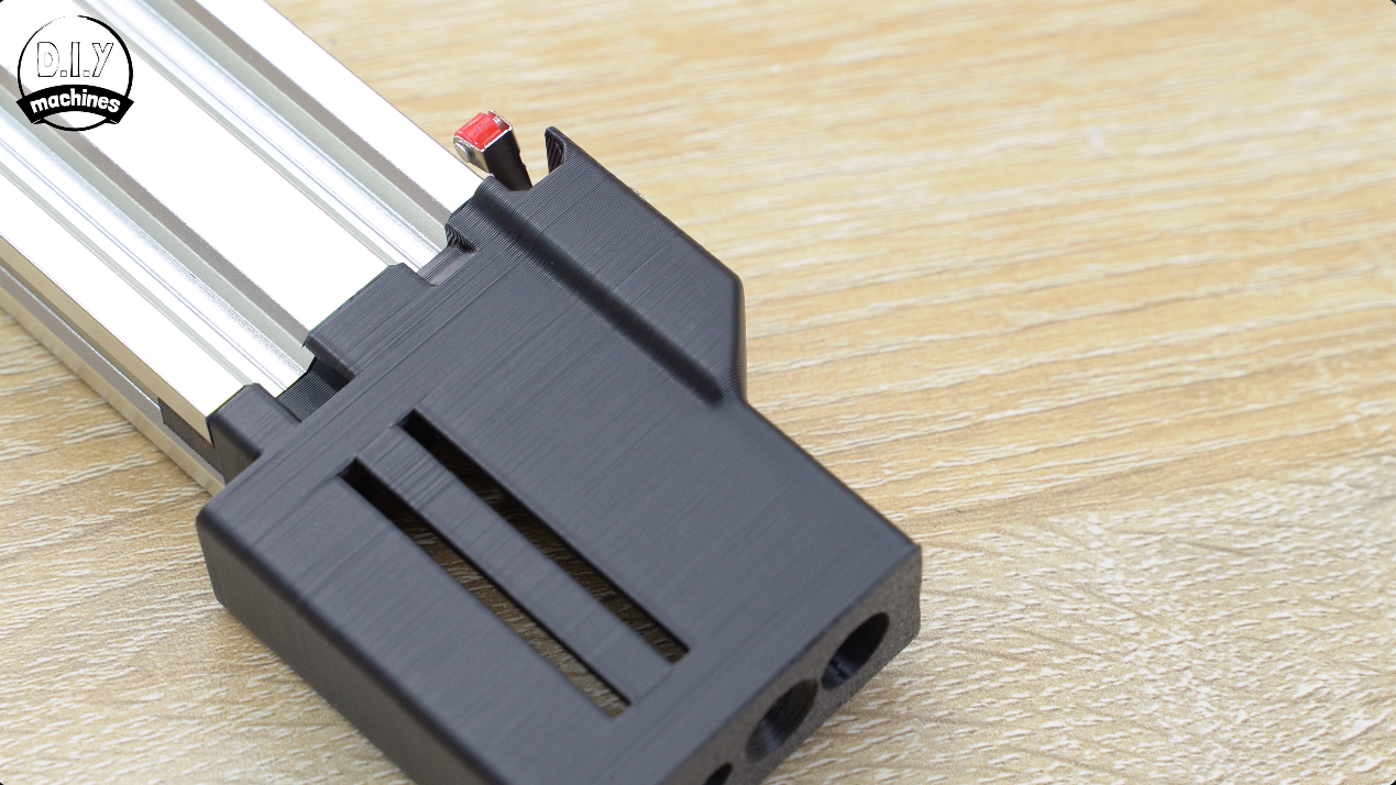
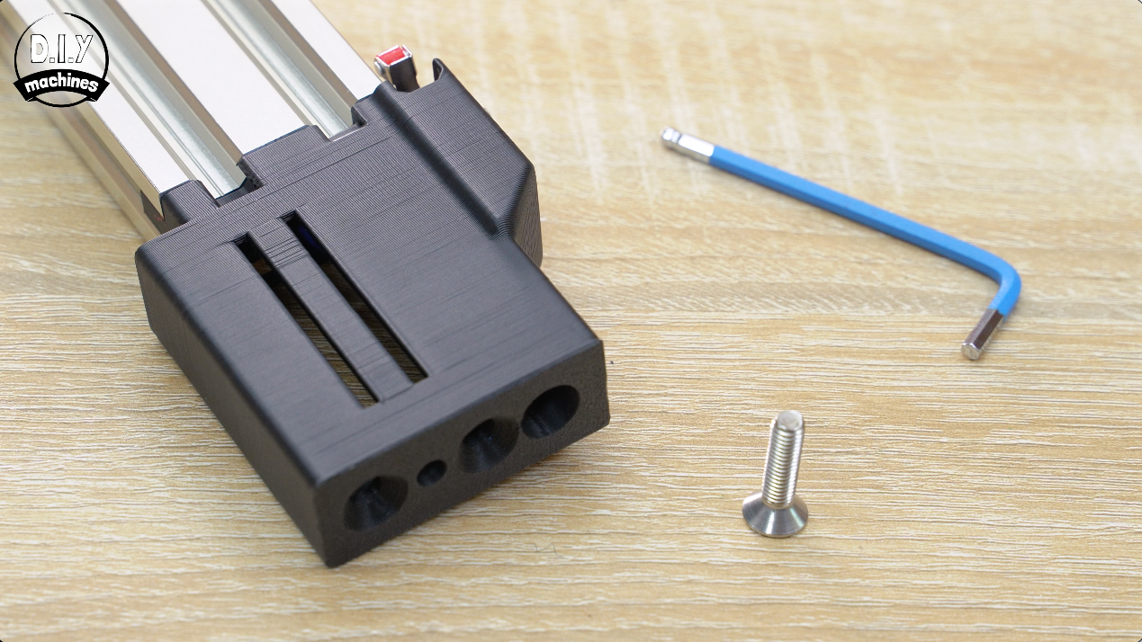
Finally, feed the wires through the extrusions central hole and insert the 3D print into the end of the extrusion.
Bolting the Idle End in Place
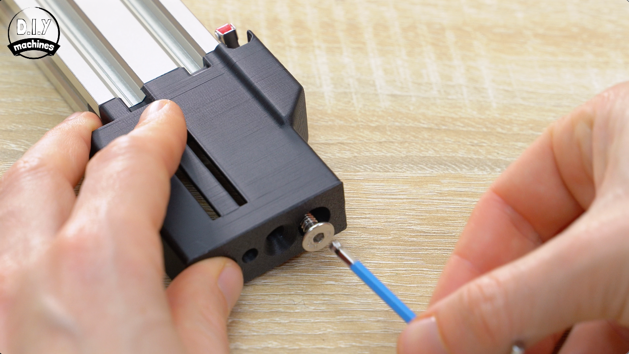
This part can then be bolted into place firmly with two M5x20 bolts. They both pass through the 3D print and into the tapped ends of the aluminium 2040 extrusion. The first goes through the deep hole, and then add a second M5x20 inside the recess and bolt in place using the access hole for your Allen key at the end.
Fitting the Idler Wheel
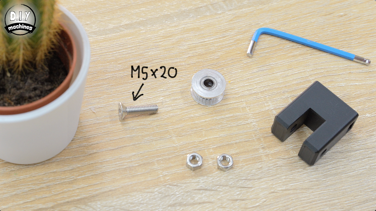
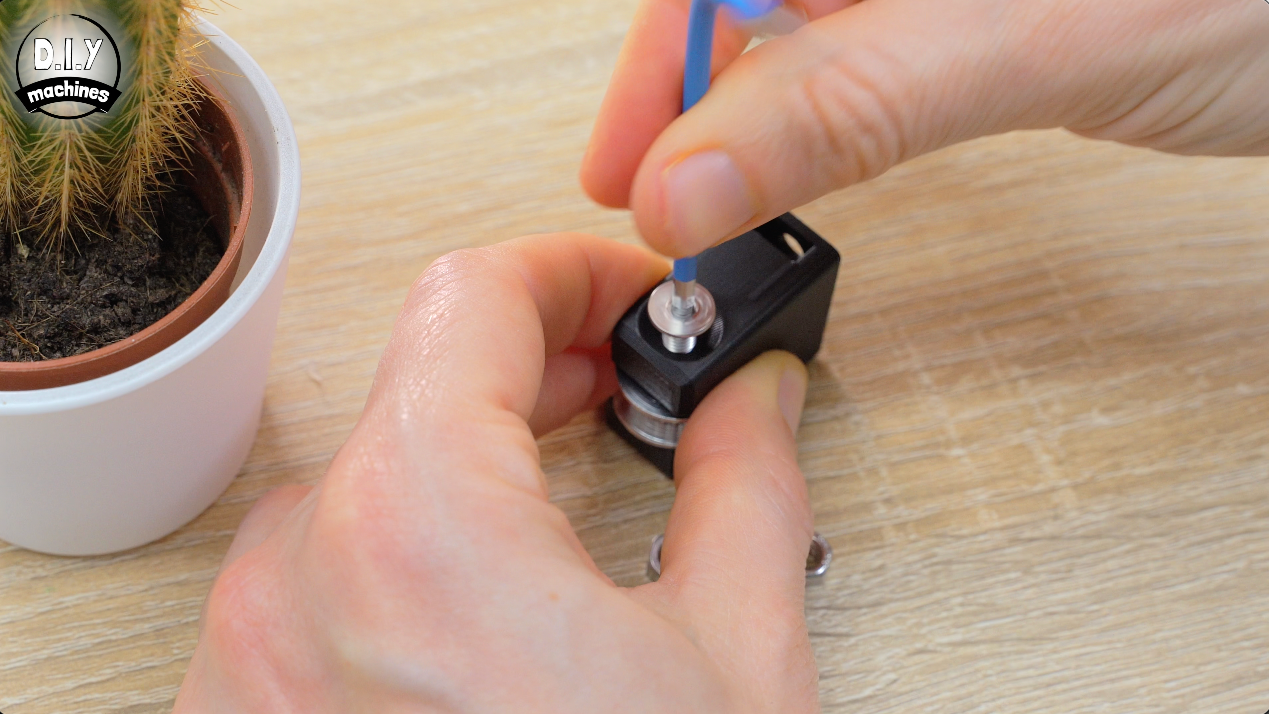
Use an M5x20 bolt to install the idler wheel inside the wheel mount.
Add an M5 nut into each of the recesses on the side ready to receive a bolt shortly. They will be a little loose until the bolt is added so try not to loose one!
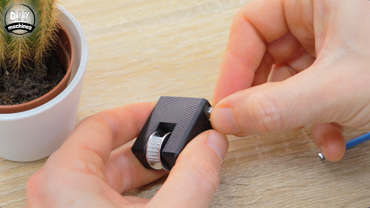
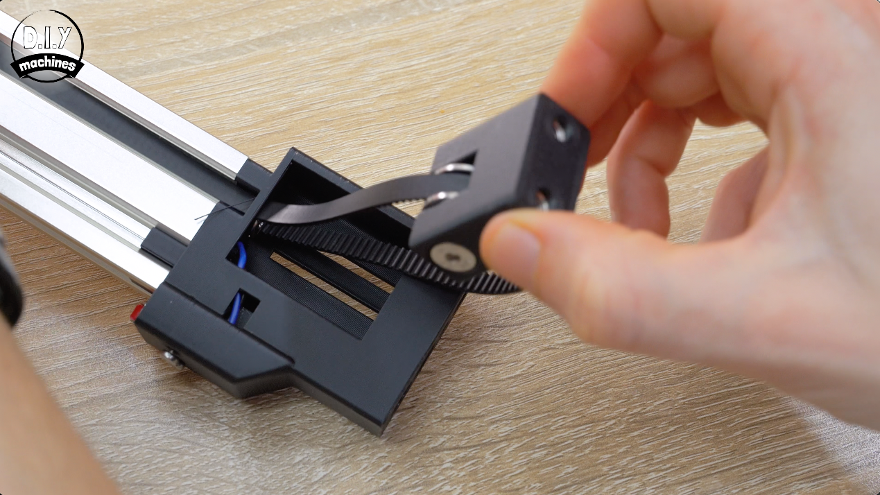
Take the timing belt and feed it around the pulley so that the teeth are on the inside. Then pass one end through the path above the bolt
in the 3D print (the one bolting it to the aluminium extrusion) and the other end under the same bolt so that the teeth of the belt are facing towards the centre of the extrusion.
Take in the slack of the timing belt on both sides and install the idler assembly down into its slot.
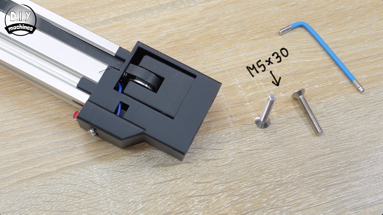
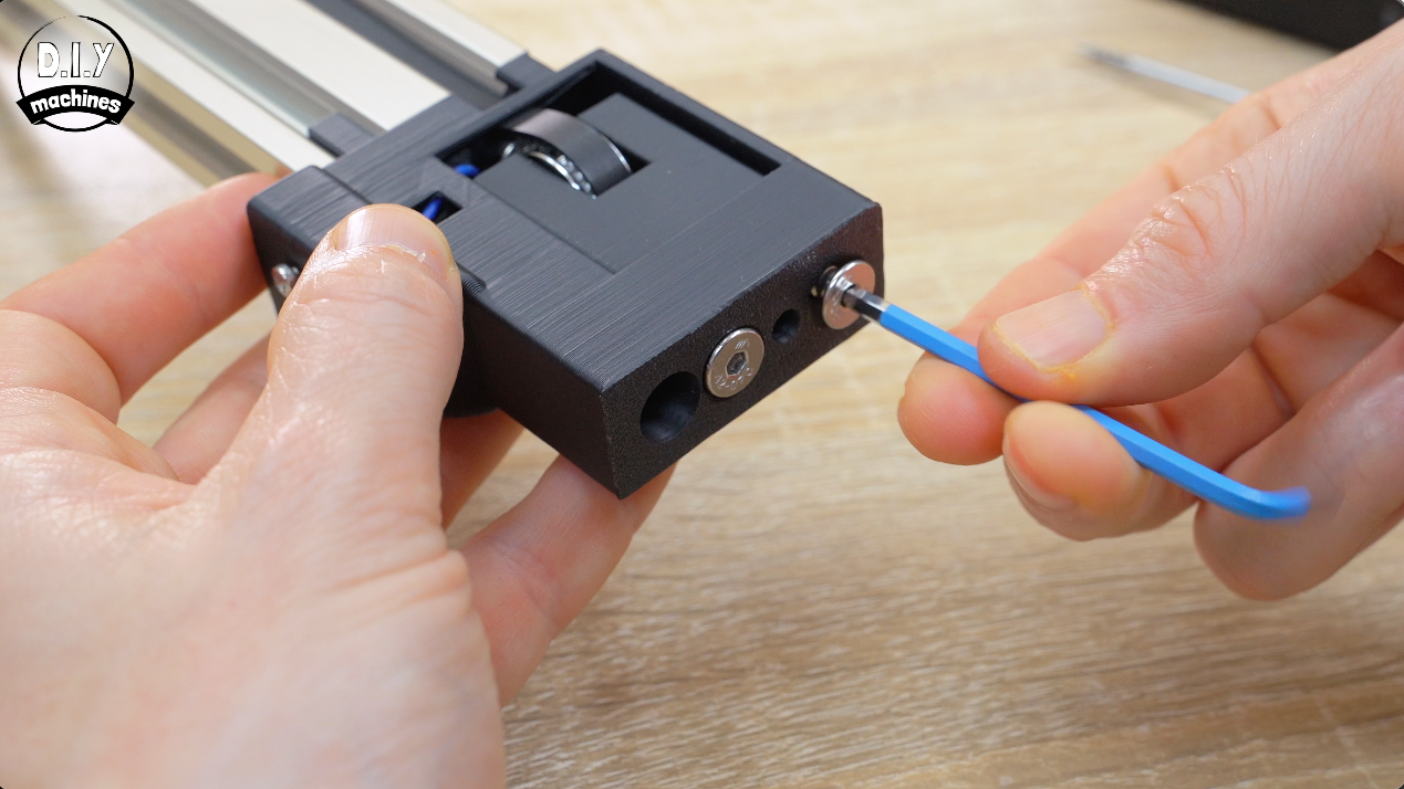
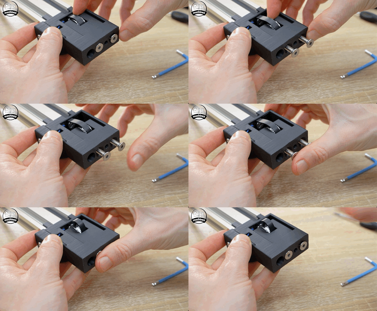
Install two M5x30 bolts to grip the idler sliders bolts but don’t tighten it yet - we’ll use this later to add tension to the timing belt.
Fitting Top End of the Timing Belt
Now we can fit the end of your timing belt on the topside into the camera platform.
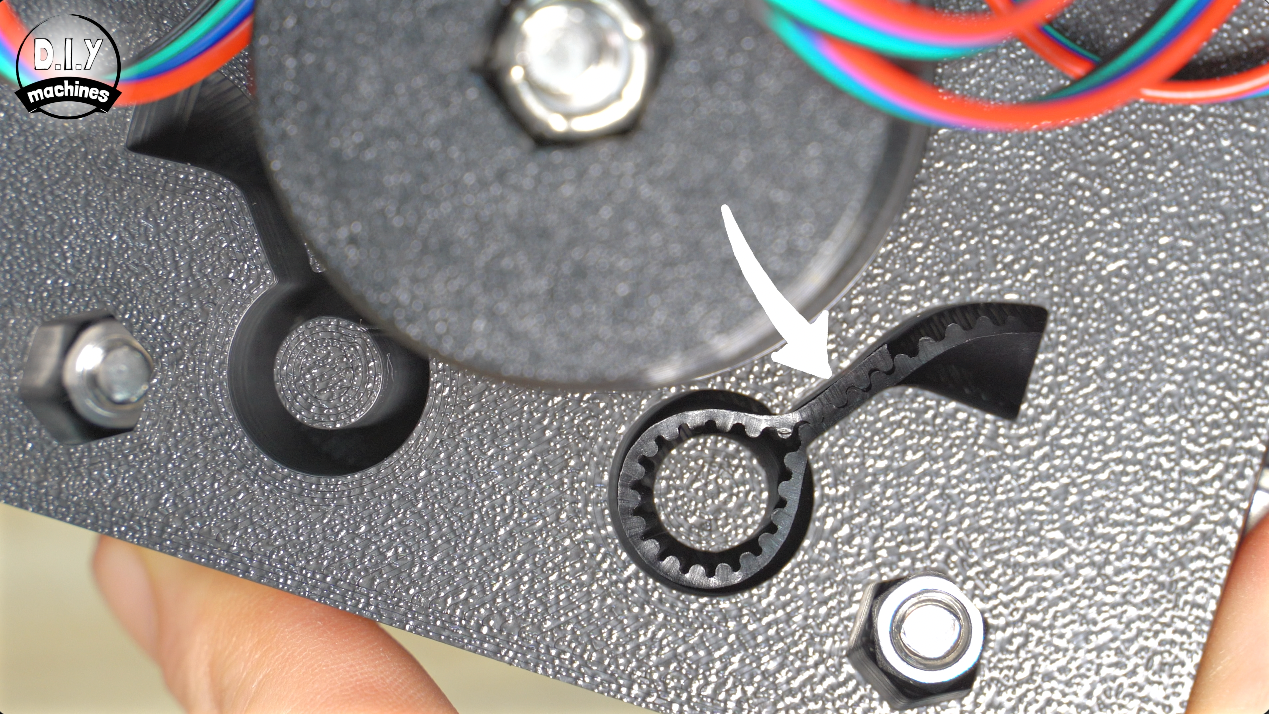
It needs to go into the same side of your camera platform that your motor wire exits. Insert it from beneath checking you have no twists in your belt and then pull a bit through to make a loop on itself with the teeth engaging both sides and then pop it in around the pin. An Allen key can be useful for pushing it back down into the recessed pathway around the pin.
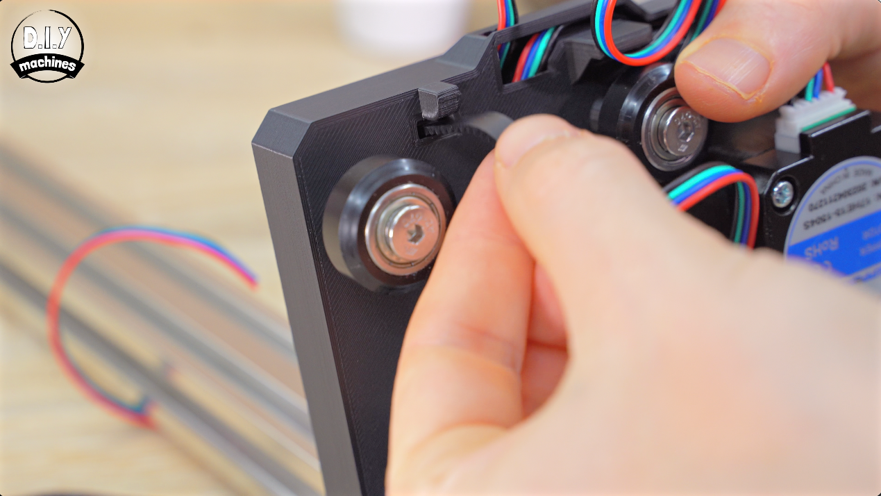
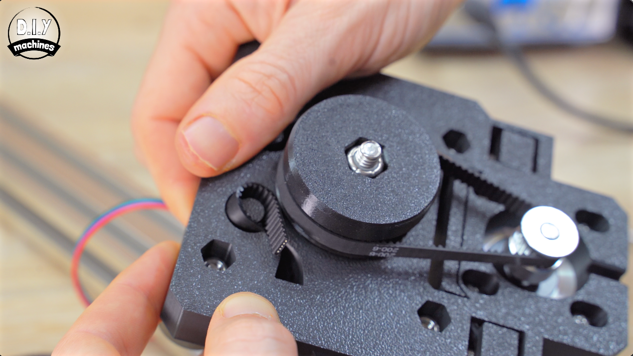
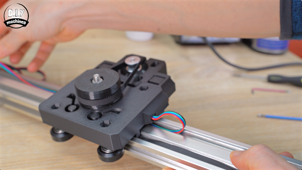
Again, whilst making sure there are no twists in the wire we can feed the stepper motor cable back under the platform.
Routing Timing Belt Through 'Powered End' Print
We’ll work on mounting the X Axis motor and some more electronics next. For the following few steps You’ll need to 3D print “X Axis Motor Mount”.
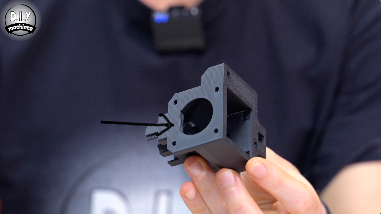
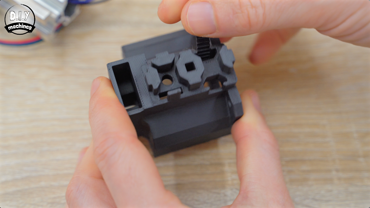
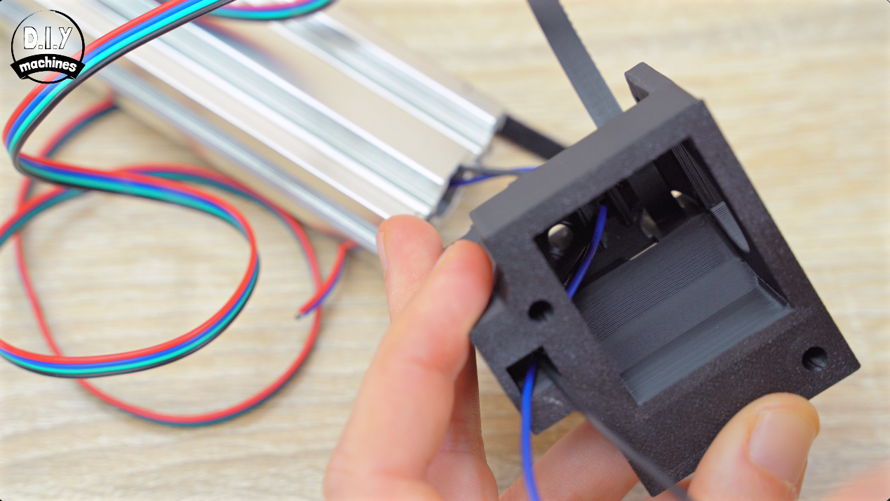
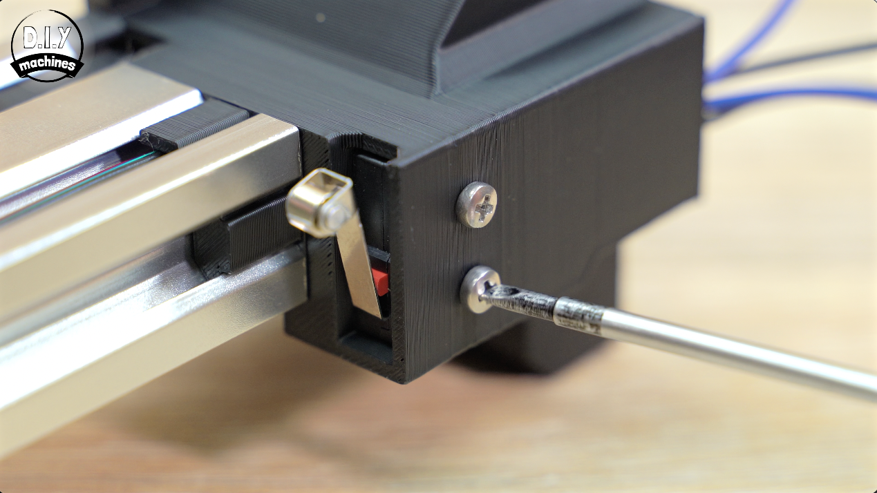
We will mount the motor on the side of the print illustrated in the first image.
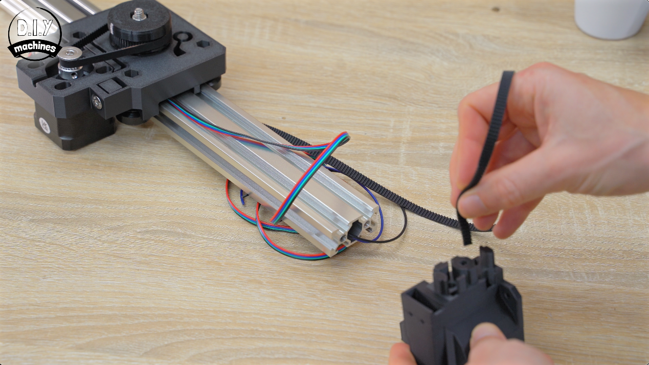
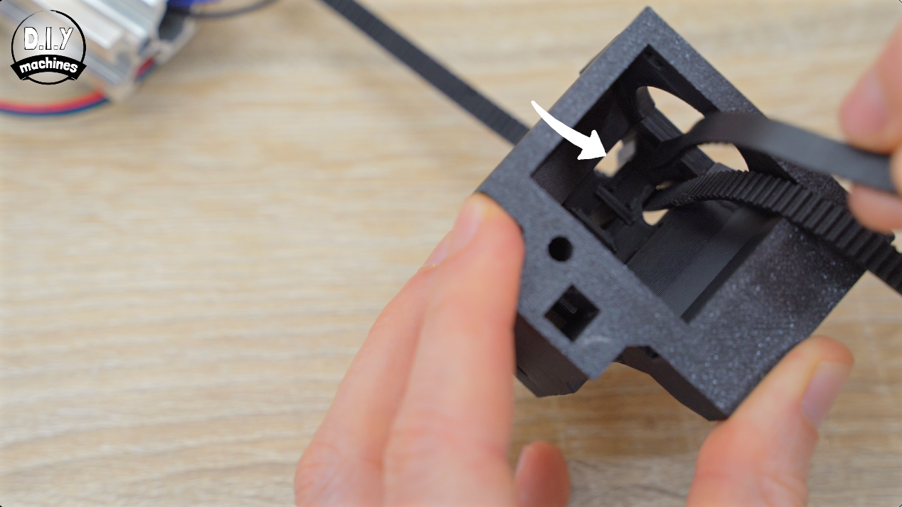
For now, place your print at the unused end of our extrusion so that the side that the motor is going to go on is the opposite side of the Y axis motor fitted to the camera platform. We can then feed the bottom end of the timing belt through the lower hole into the print and then back out through the upper hole.
Routing The Contact Switch Wires Through 'Powered End' Print
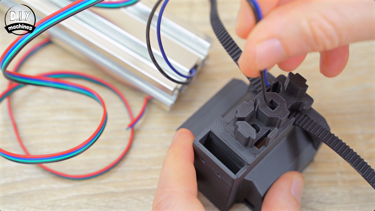
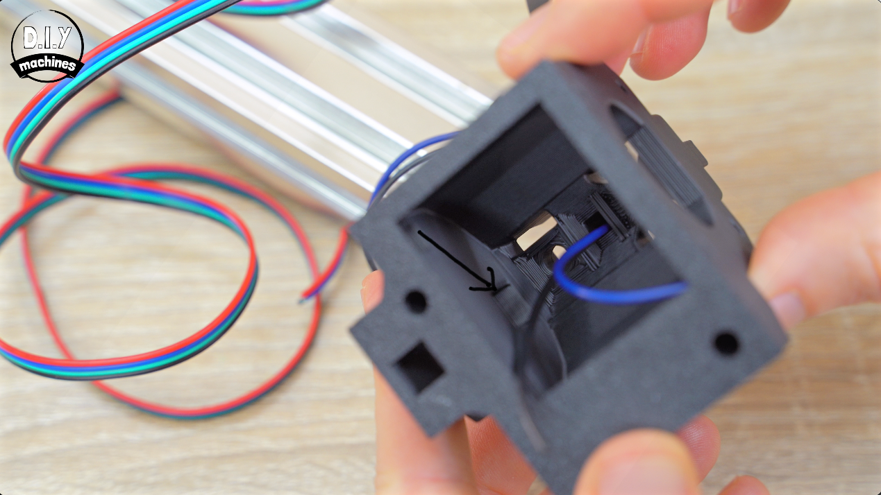
Feed the Contact Switch's wires from the central hole of the aluminium through the central hole in the 3D print. Then they enter the side channel and exit out away from the extrusion.
Finish Attaching The 'Powered End'
Slide the gantry off the extrusion just enough to pass the other end of the timing belt through the print. Again, make sure you are not introducing any unwanted twists into the timing belt.
Slide the gantry back on the extrusion then bring the X motor mount around, and then slide onto the end of the end of the extrusion.
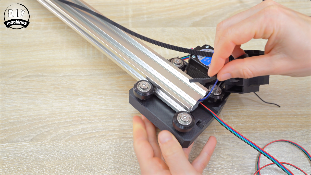
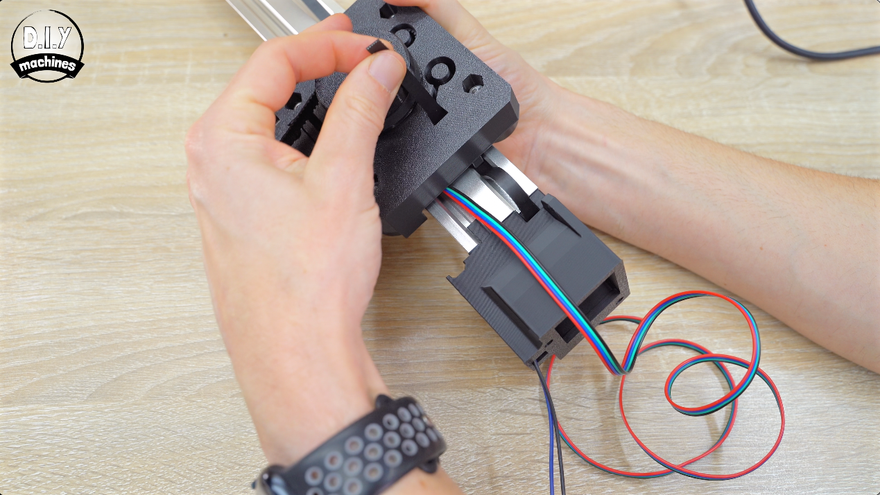
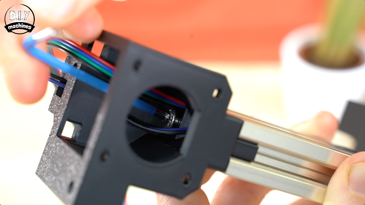
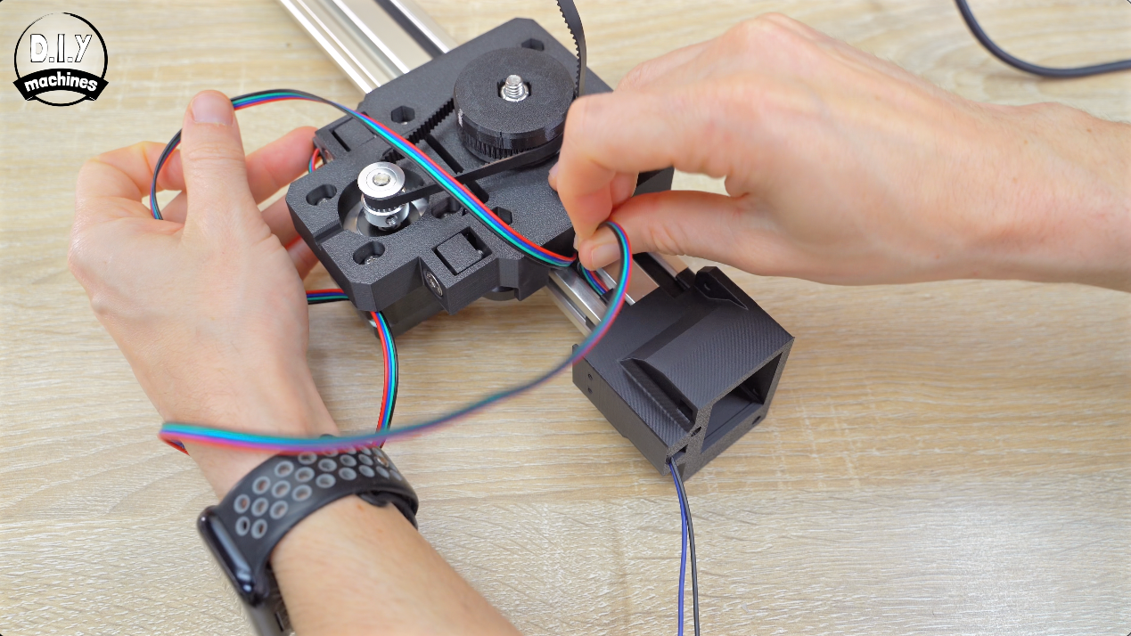
Feed the Y axis motor cable along the extrusion and through the 3D print. (I'm sure you know by now to make sure you're not introducing any unneeded twists in the cable 😉).
Don’t panic if you have a lot of slack in your timing belt at the moment - we will sort this later on in the build.
Use an M5x20 bolt to secure this print firmly to the extrusion.
Adding Second Limit Switch
Solder a pair of 16cm long cables to the NC (Normally CloseD) and C (Common) pins of your remaining contact switch, then thread this through the 3D prints channels and secure with your last two M2.5 x 8mm bolts.
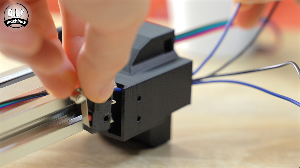
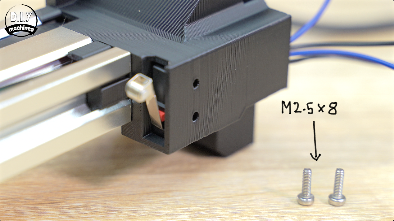
Attaching X Axis Stepper Motor
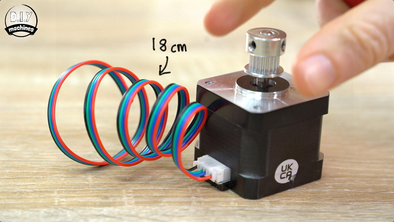
Attach a toothed pulley onto the second stepper shaft, this time with the teeth closest the motor but still seated flush with the end of the shaft ensuring again that the grub screw is tightened against the flat face of the shaft.
Attach the power cable and shorten it to 18cm in length.
Create a loop with the timing belt inside the 3D print, and wrap this around the teeth of pulley as you insert the motor shaft and pulley from the outside.
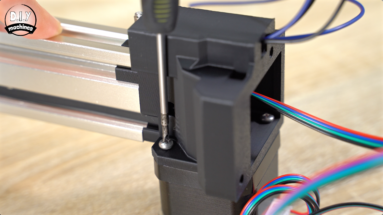
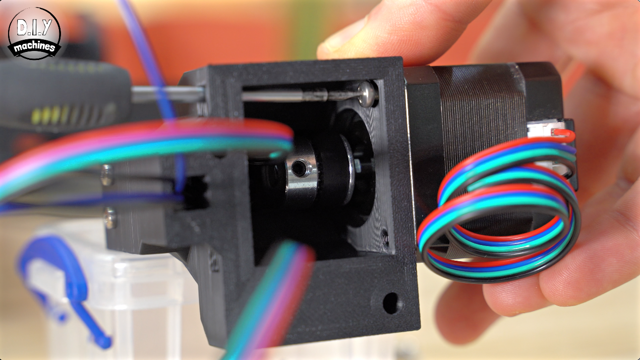
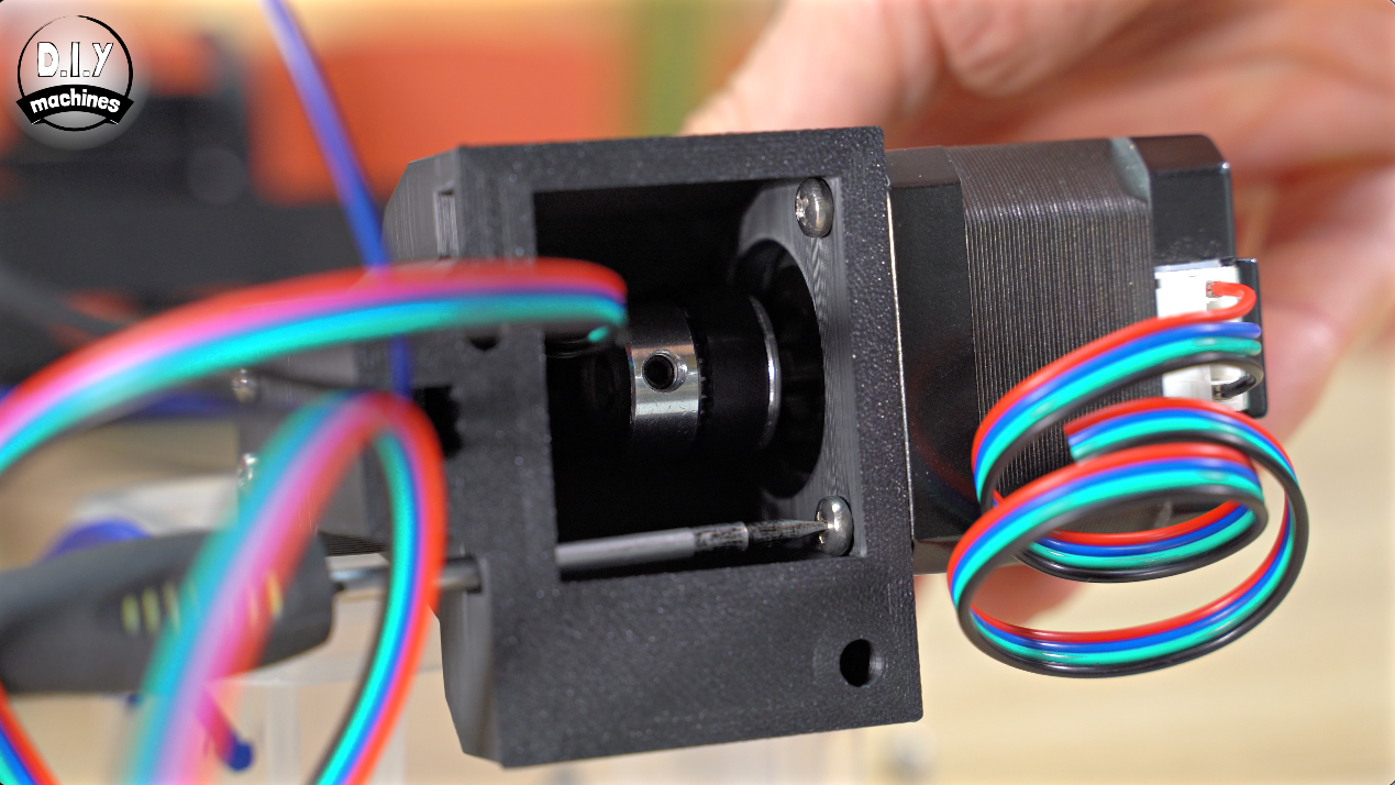
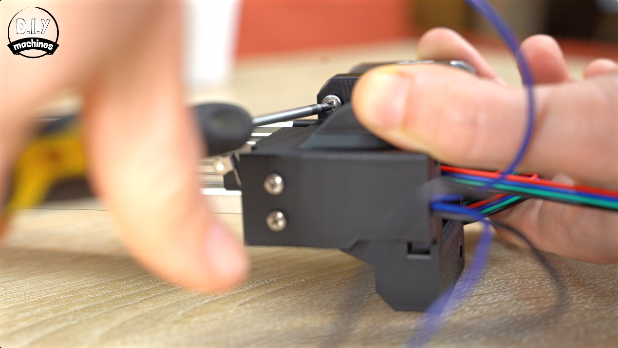
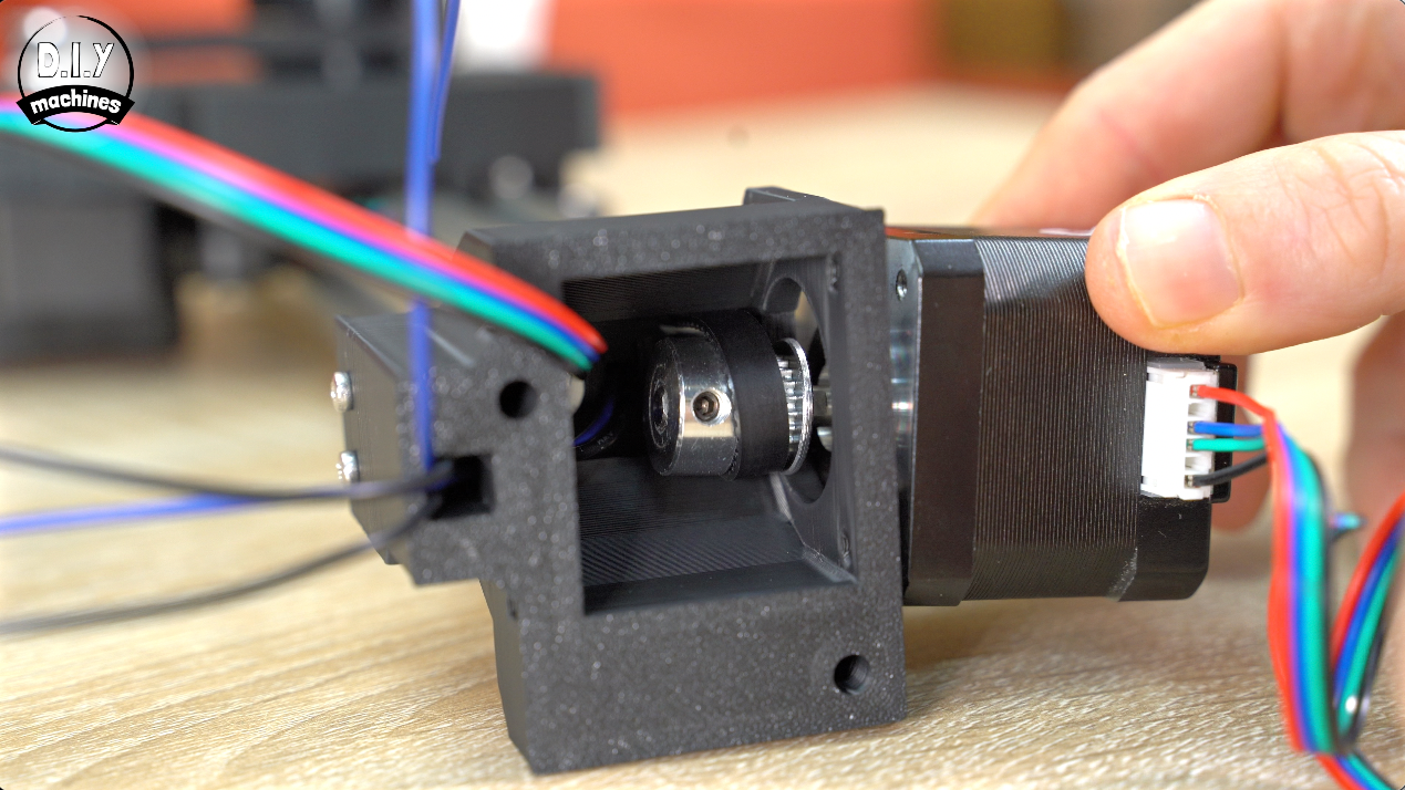
With the motors cables leaving the side of the motor furthest from the extrusion secure it in place with four M3x 8 bolts. (I have added two access holes to make adding two of the screws more convenient).
Attaching 2nd End of Timing Belt and Tensioning
As we did earlier with the other end of the belt. You can now pull the timing belt tight (as much as you can at for the moment) and loop it around the pin in the cameras platform. If you have too much excess you can trim it off.
Going to the idle end of the extrusion we can add some tension to the belt using those adjustment bolts we added earlier - again we need just enough so that a couple of steps turning the stepper motor by hand instantly shows up as a change in direction of the platforms movement. We want to avoid any backlash or slop.
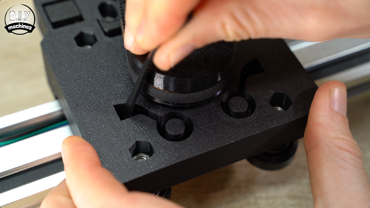
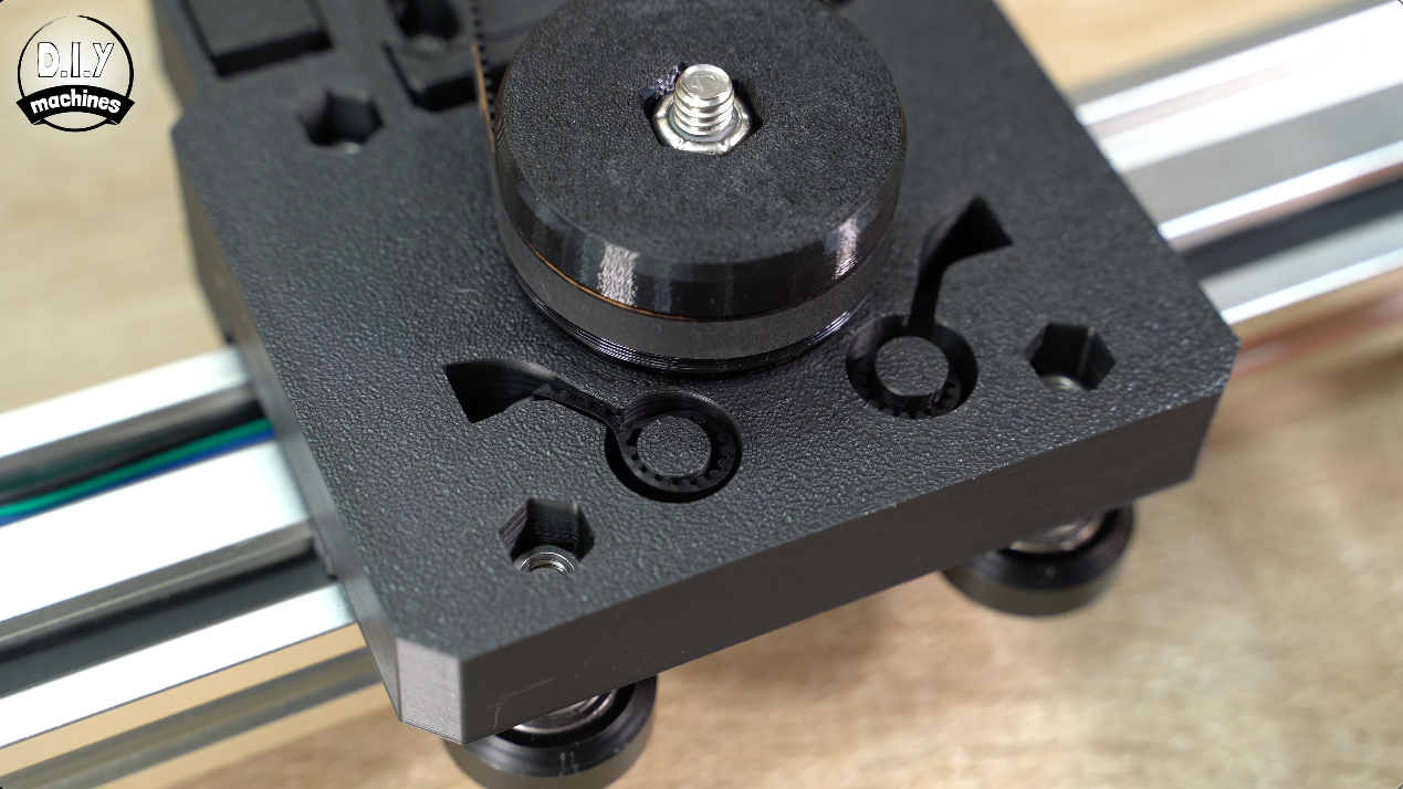
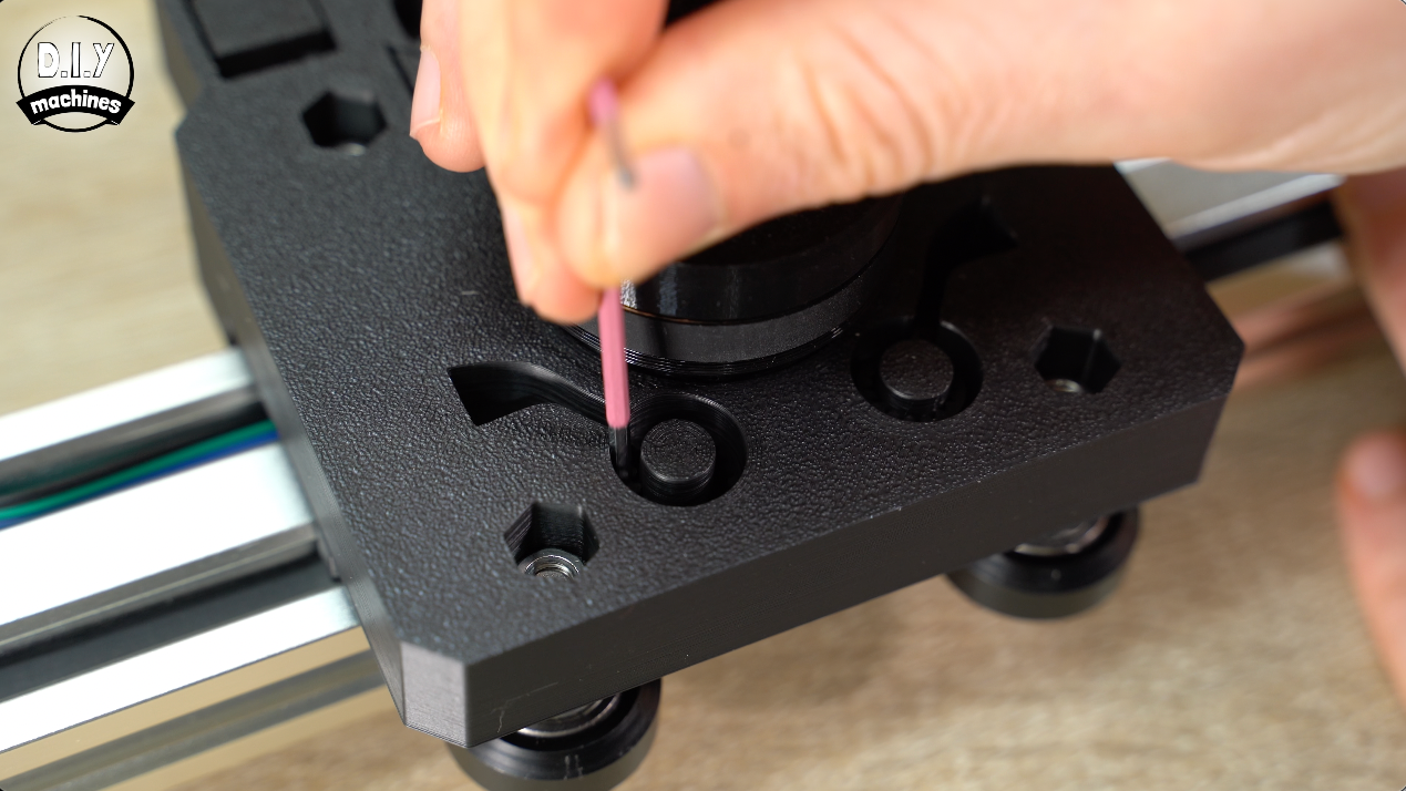
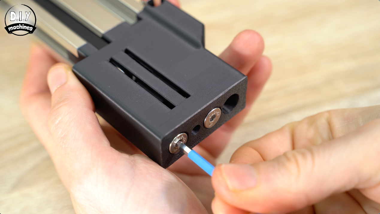
Ensure you adjust the two bolts equally.
Electronics Enclosure
Next, you’ll need to print the ‘Electronics Box’.

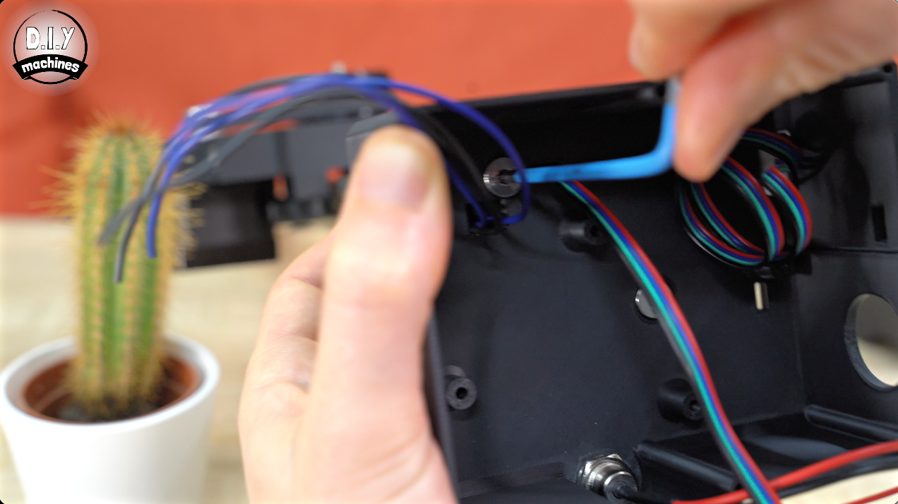
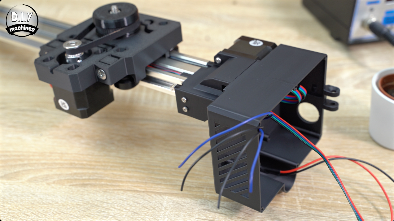
We’ll add the DC Power Barrel to this before sliding all the other cables through the openings in the rear of the case and securing it with two M5 x 14 bolts from the inside.
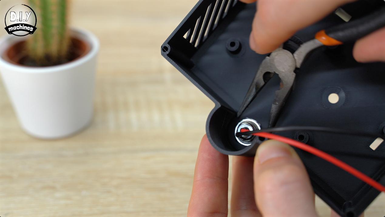
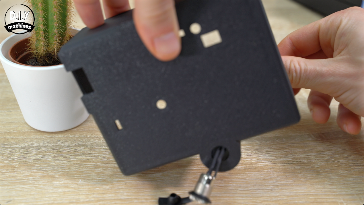
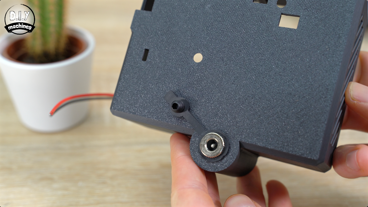
Now we have the electronics enclosure attached let’s prepare the electronics themselves.
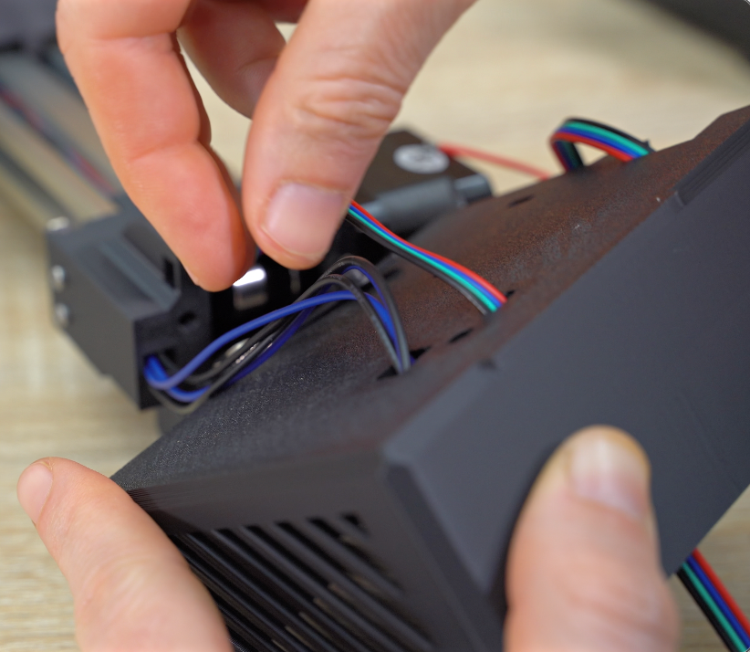
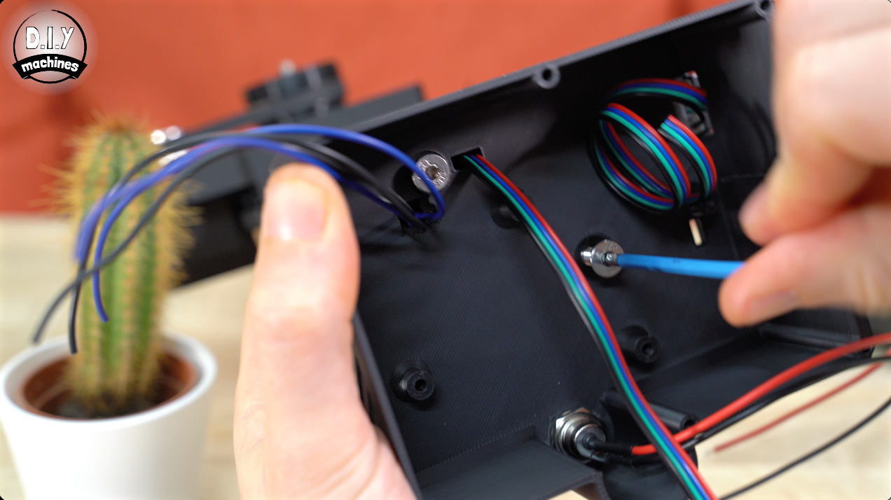
Preparing the PCB
I’ve designed a custom PCB which significantly simplifies the wiring. It’s clearly labeled with which component should go where along with polarity where it matters most.
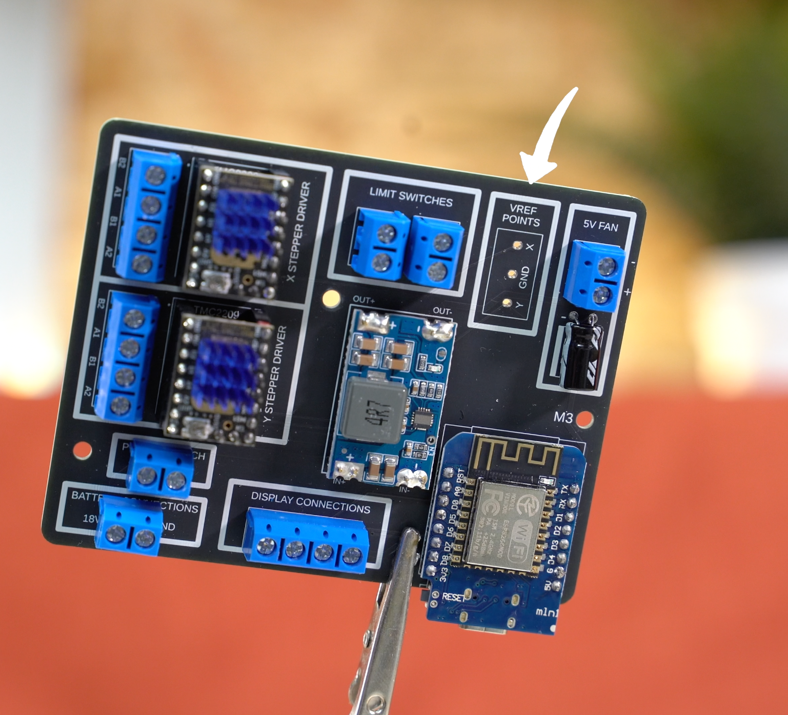
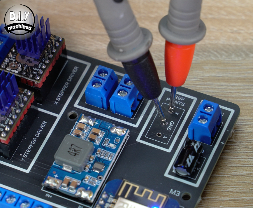
I’ve also added some additional features such as probe points to conveniently set the voltage reference of our stepper drivers later. The PCB is optional, and as mentioned earlier I have linked a wiring diagram above if you want to wire it up your own way.
You can order a PCB either from PCBway directly or from my international Etsy shop where I stock all the PCBs for my projects as well as kit’s with all the electronic components you’ll need as well.
Let’s go over the assembly of the electronics now.
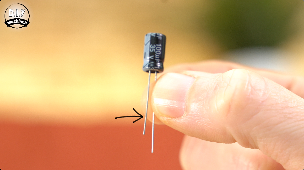
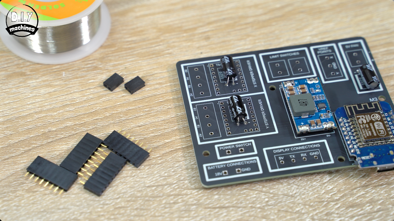
We’ll solder the three capacitors in place first paying intention to the polarity. The negative leg is shorter and marked with a stripe on the capacitors body. This is shown on the PCB with the negative mark and matching white stripe.
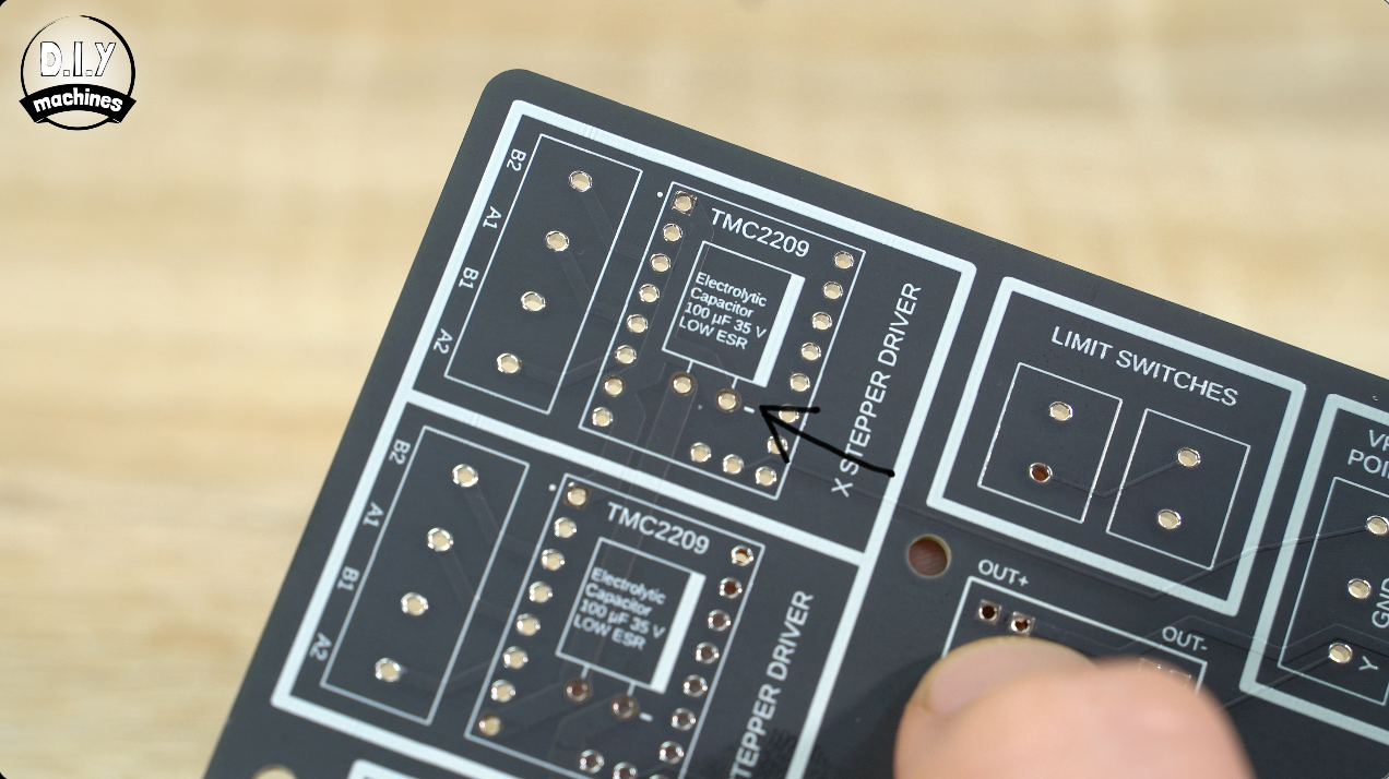
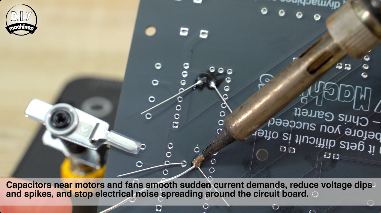
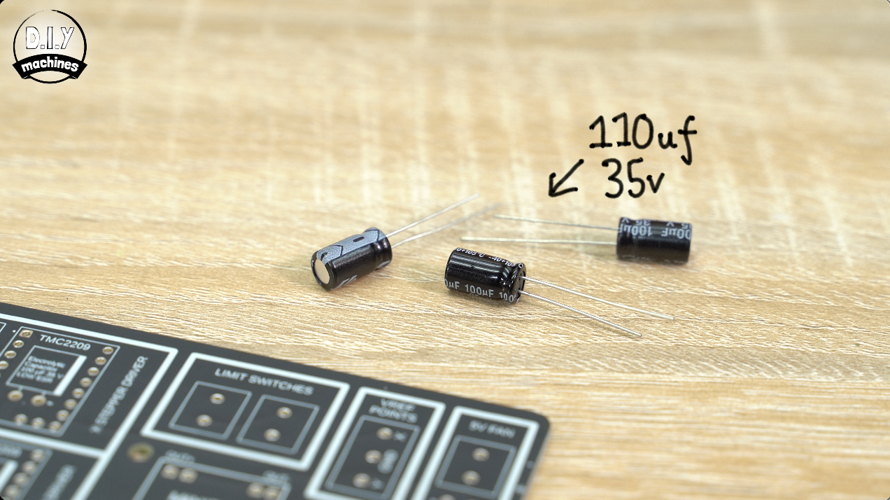
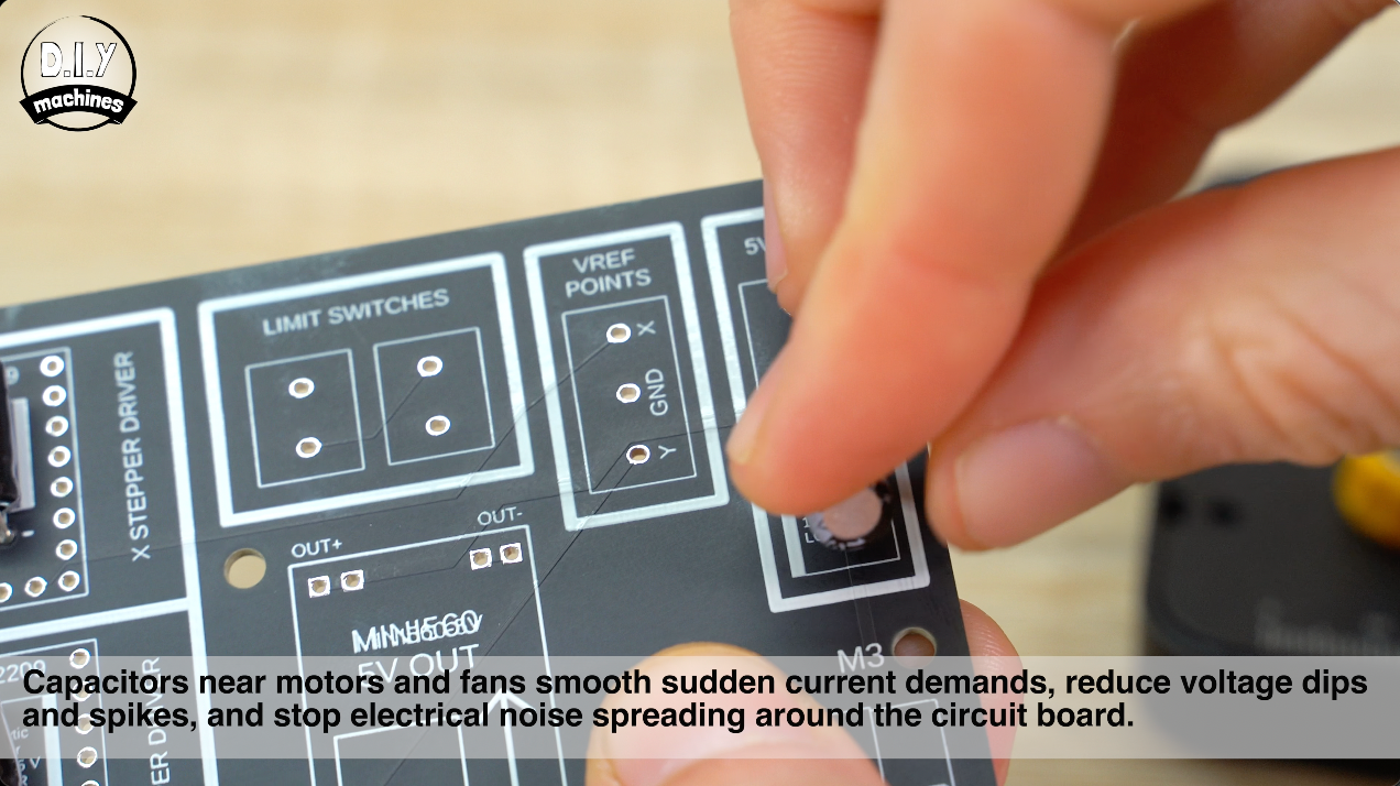
Two of the capacitors go in the top right (for the stepper motor drivers) and another in the top right near the optional 5v fan.
Capacitors near motors and fans smooth sudden current demands, reduce voltage dips and spikes, and stop electrical noise spreading around the circuit board.
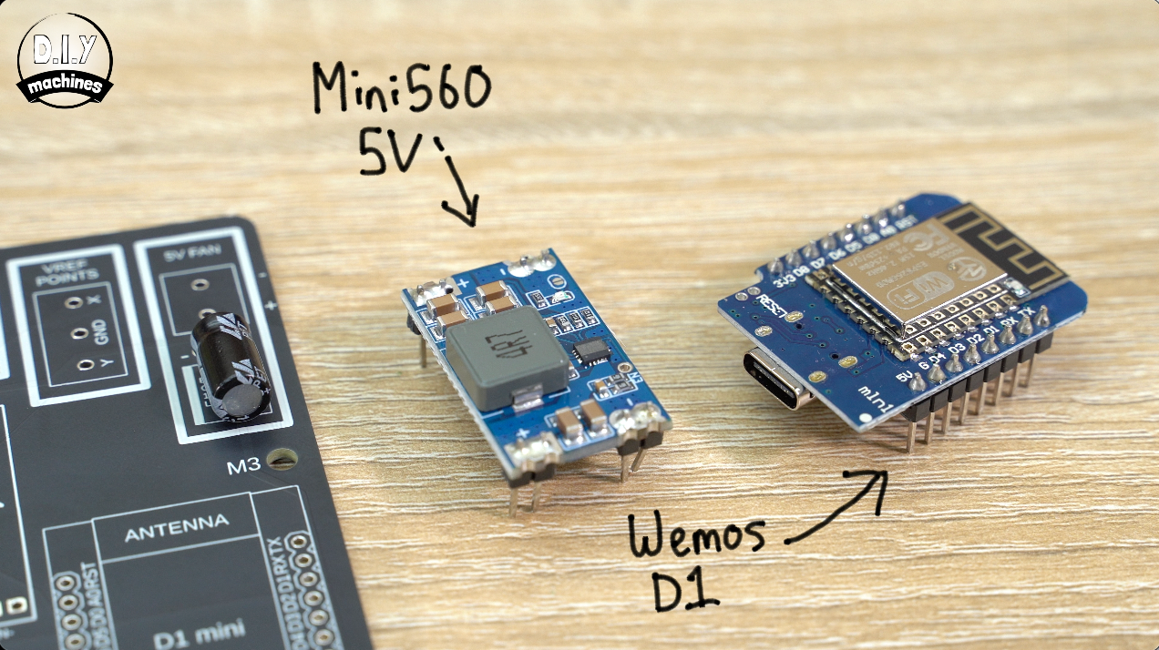
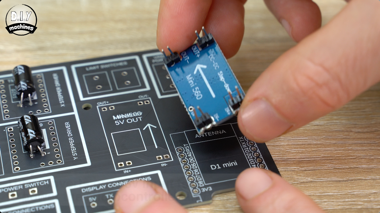
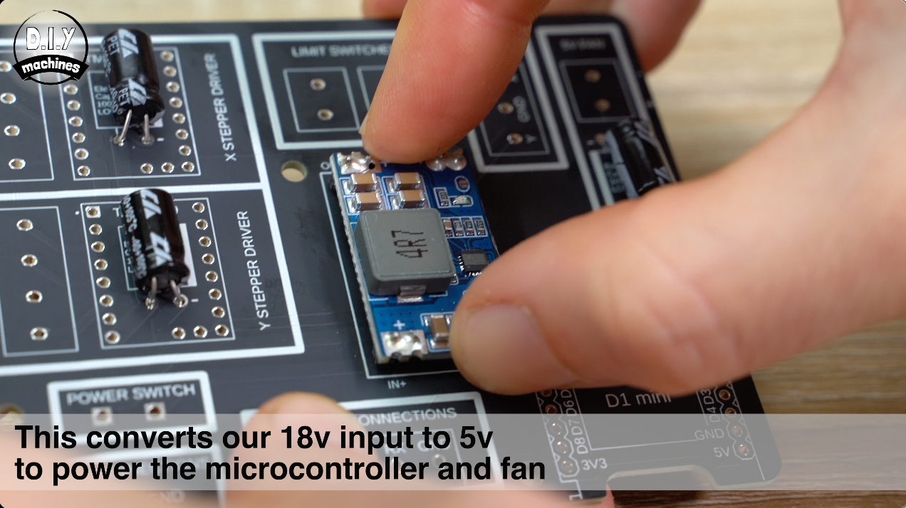
Next is the 5v Mini560.
Ensure the arrow on the underside of the Mini560 matches that printed onto the PCB. This component generates 5v for the fan and Wemos D1 from the 18v power supply our project uses.
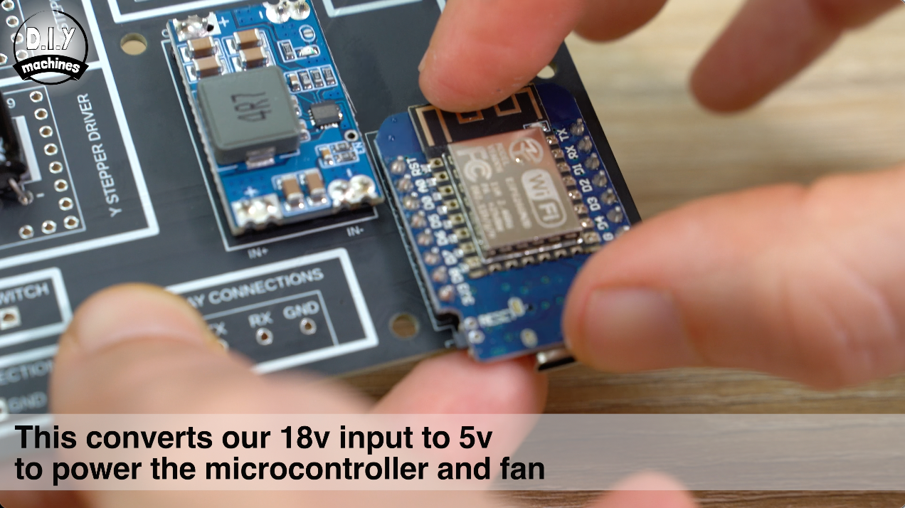
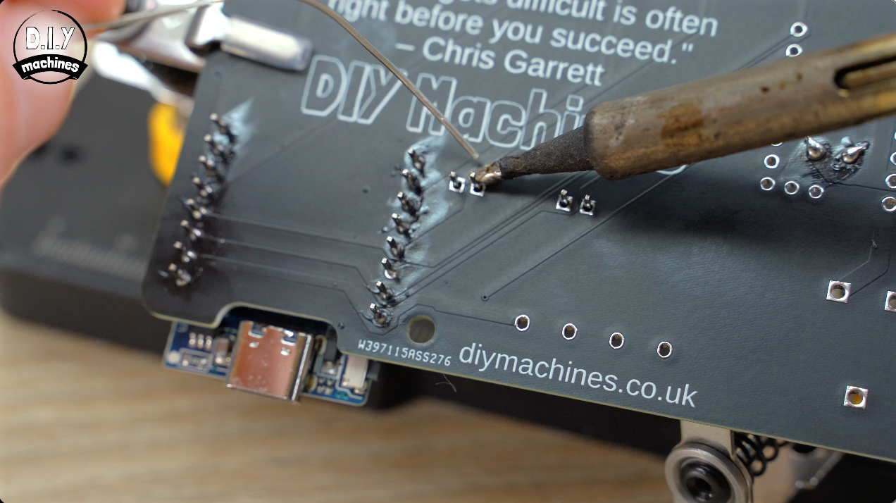
The Wemos D1 is added in the bottom right and all of its pins are then carefully soldered in place on the reverse side. This is our 'Motion Co-Porcessor' if you like - it takes commands from out touchscreen interface and turns them into movement on our slider. It also handles homing and monitoring limit switches.
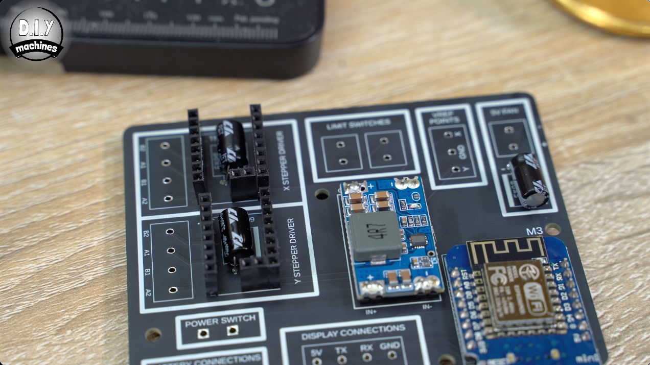
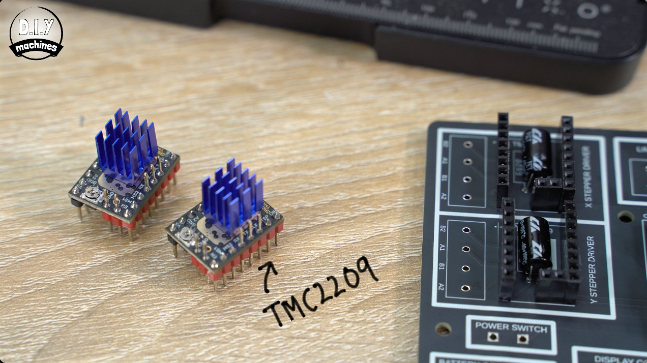
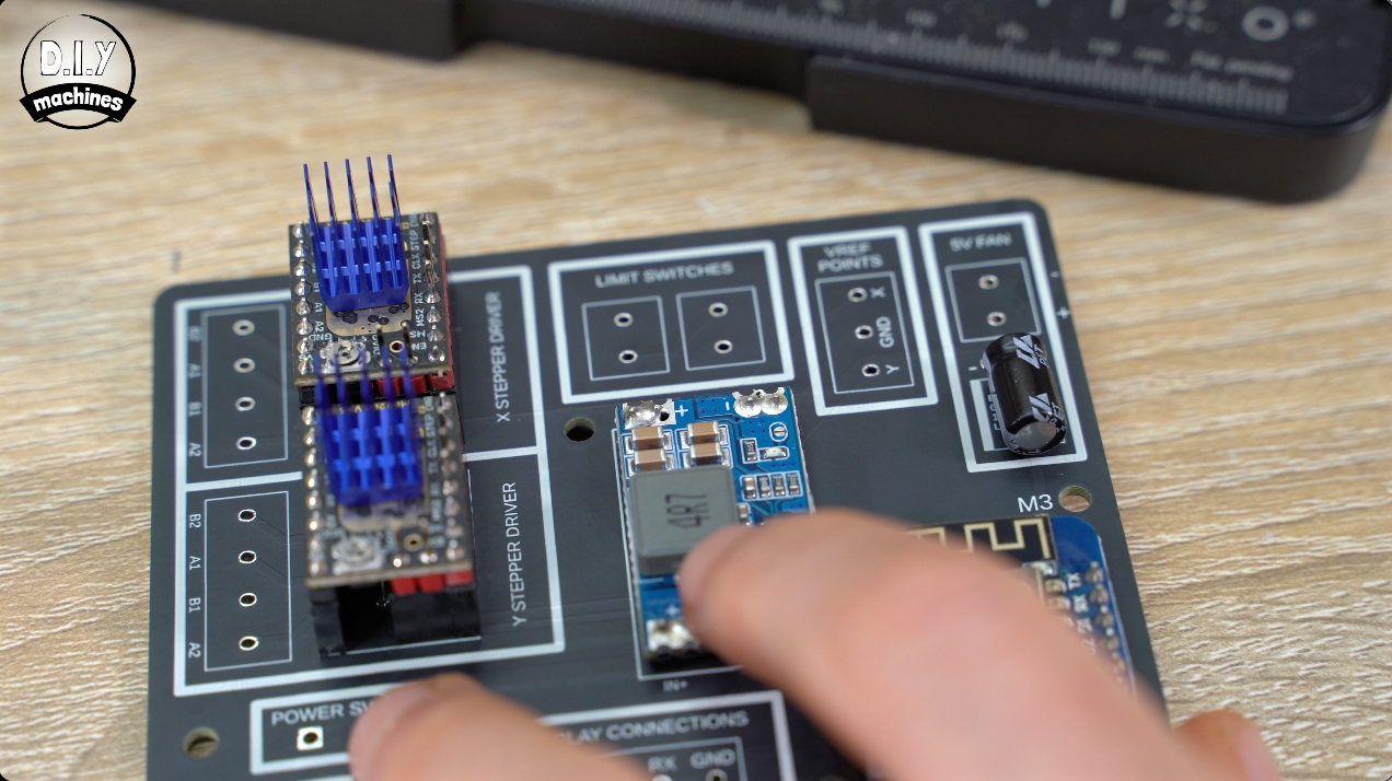
The stepper drivers need to sit above the capacitors so we will solder some male headers into place. Then we can pop the motor driver boards onto these, and their heat sinks on top of this ensuring that they do not short any pins.
Optional: Wiring Blocks
You have a choice for how to connect all the wires to the PCB.
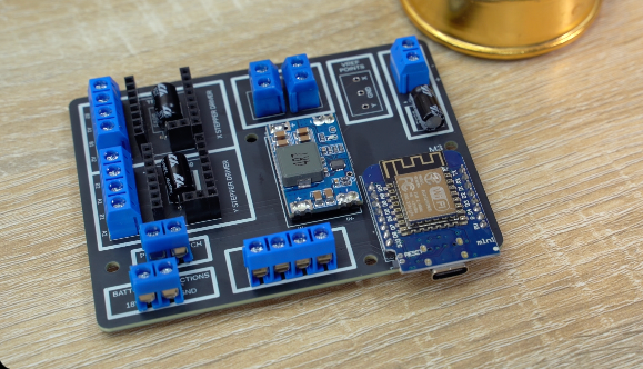
You can either solder them on directly to the PCB, or solder screw headers into place and attach the wires with those. That’s what I decided to do (it also made it easier for me when designing and testing the prototypes of this project). Ensure you face the wire aperture in the best direction so as to be able to attach the wires with ease later. :)
Programming the Wemos D1
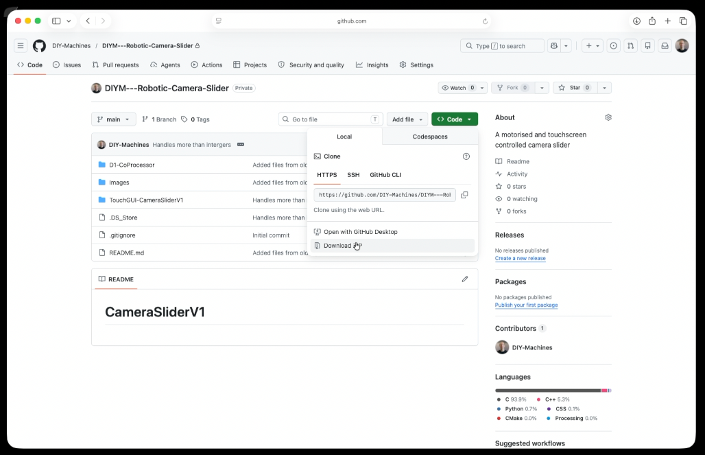
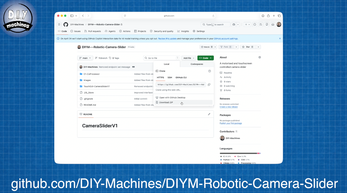
You can download the code from my Github page: https://github.com/DIY-Machines/DIYM-Robotic-Camera-Slider
Open the folder D1-CoProcessor and then the file D1-CoProcessor.ino in the Arduino IDE. Check your ‘sketchbook location’ in the Arduino IDEs settings is the same folder this .ino file is in.
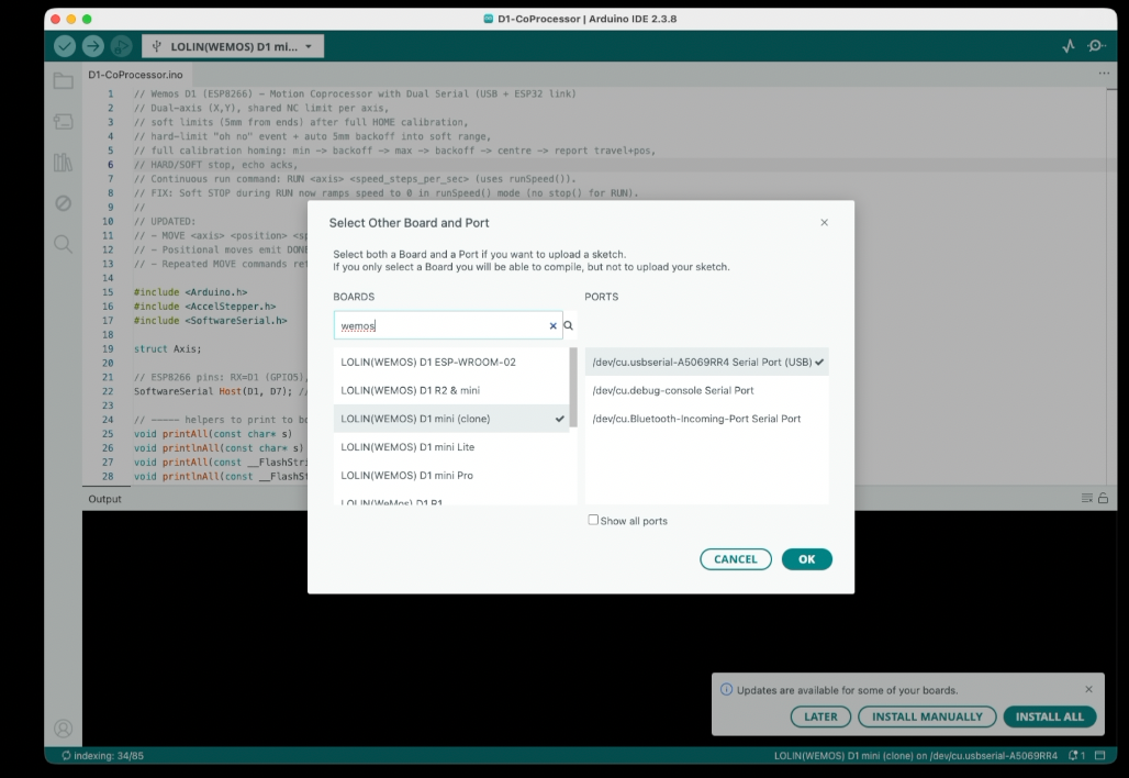
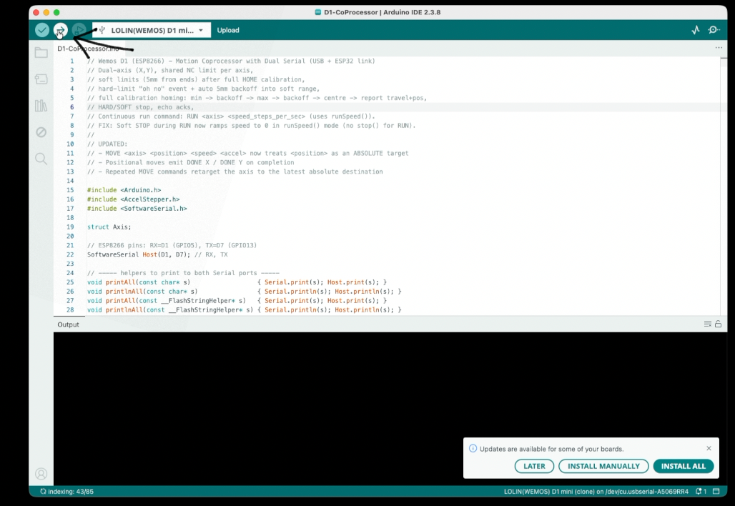
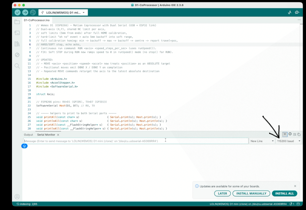
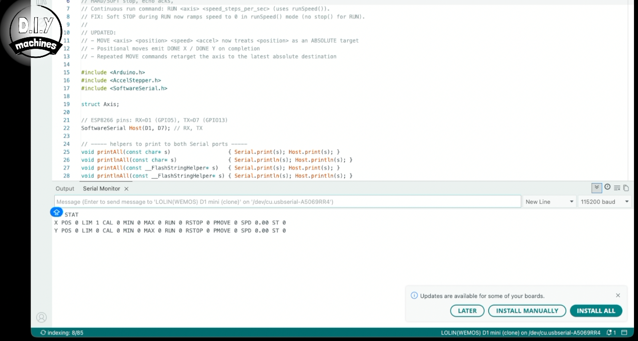
We can then set the board type as ‘Wemos D1 Mini Clone’, select your serial port and then press upload.
Once uploaded you can verify it works by opening the Serial Monitor, set the baud rate to 115200 and send the command ‘STAT’ in capitals and you should get a response from your microcontroller.
If that works we can unplug it and set the Vref point of our stepper drivers.
Setting Stepper Drivers VREF Value
So what is the 'VREF'?
This is a reference voltage on our stepper drivers that sets the maximum current the driver will allow through the stepper motor’s coils. To do this, temporarily connect a short length of wire between the two power switch terminals here and connect 18v to power connections in the bottom left paying attention to the polarity.
This could be via the barrel connector, with a desktop lab power supply or if you have neither of these you can skip ahead in this article and assemble the optional Ryobi battery pack for the project and then come back and use that for your power supply. (That's what I am doing).
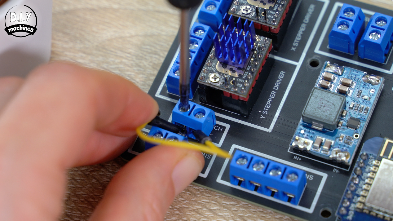
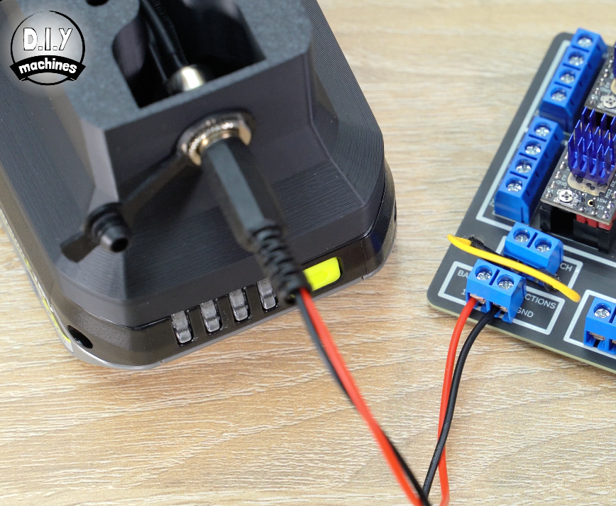
With 18v connected, be mindful not to short any power connections. We’ll be protected from this once we have finished assembling the housing.
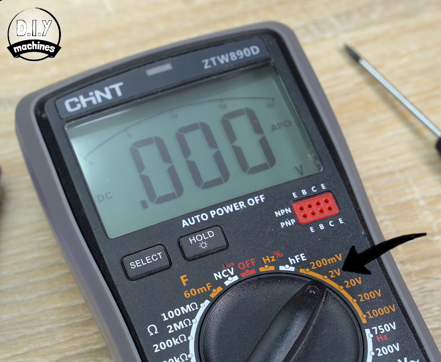
You’ll need a multimeter set to 2v DC, on mine that’s the position markers with the arrow. I have added some convenient measuring points onto the PCB.
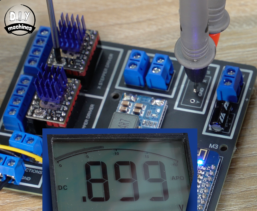
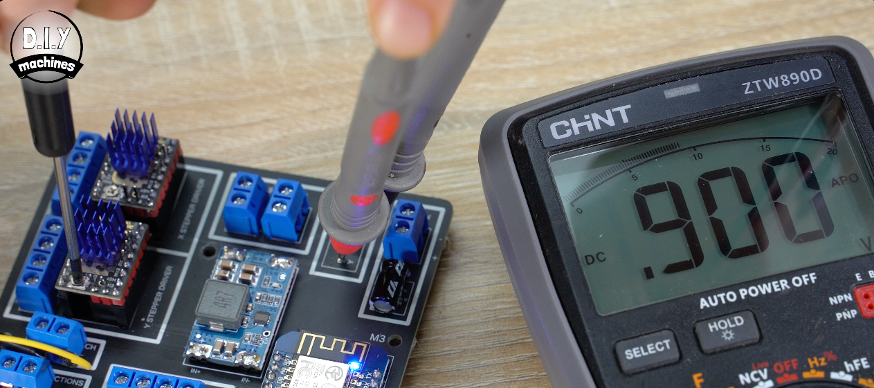
We can touch the ground probe to the GND pad, and then the positive to the pad for the X axis stepper. Then use a small screwdriver to set the value on your multimeter to 0.9v by turning the potentiometer on the stepper driver.
With this done, move the positive probe to the Y axis point and do the same for the Y axis stepper. Now we can disconnect the power and connect all these wires to the PCB.
Attaching the Wires to our PCB circuit
All the connection points are labelled. of course I’ll go through them one by one with you now anyway.
We can start with the two limit switches, ensure each switch goes into it’s own pair of connections, but it does not matter which way the Normally Closed and Common wires are connected.
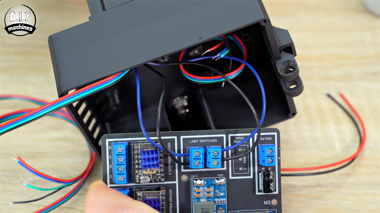
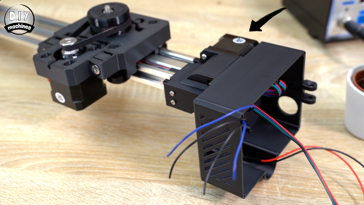
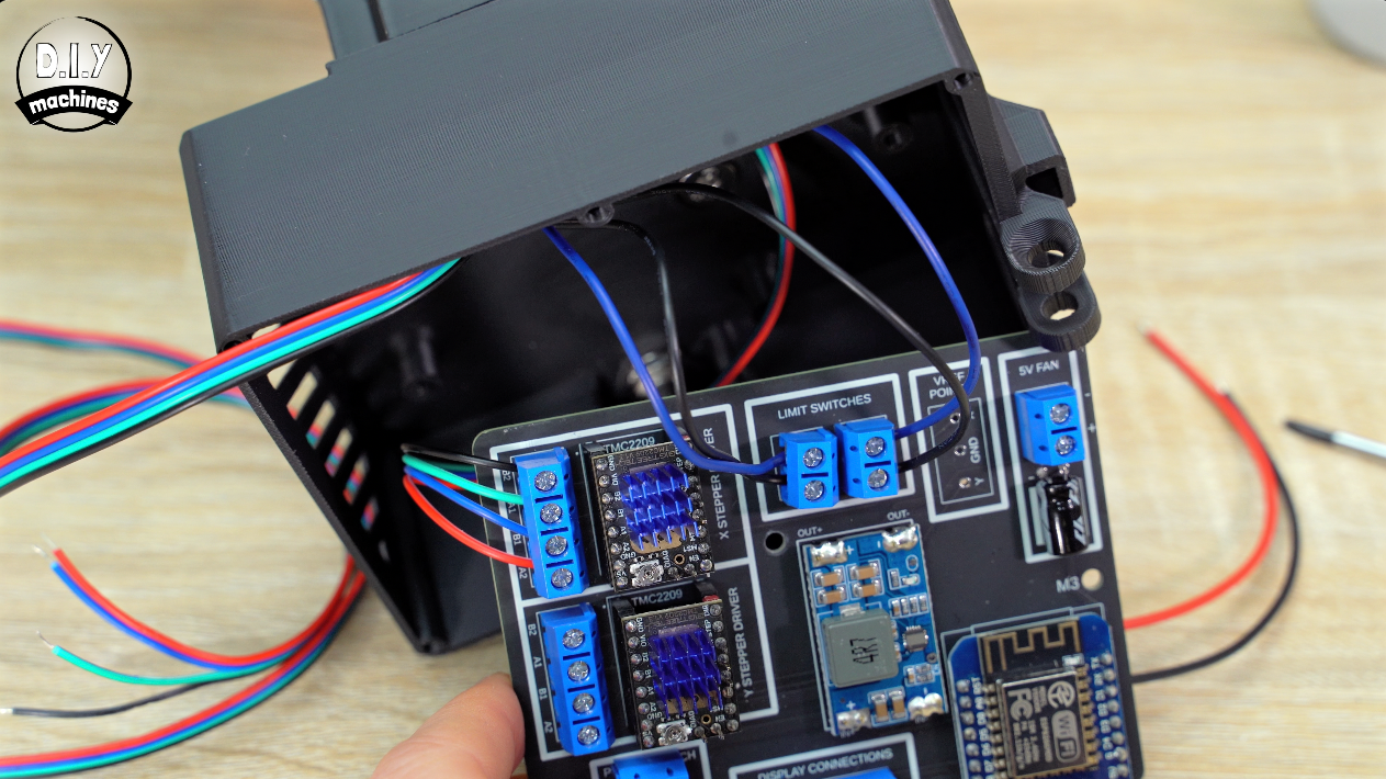
The steppers are next, the X axis one (that’s the motor next to the housing we're working on), is connected to the top driver.
If you are using the same steppers as the ones I linked to from SteppersOnline then the Stepper wire connections are as follows
B2=Black A1=Green B1=Blue A2=Red
The wiring is then the same for the Y axis to it’s stepper driver below the X Axis' one. (They are also labelled on the PCB).
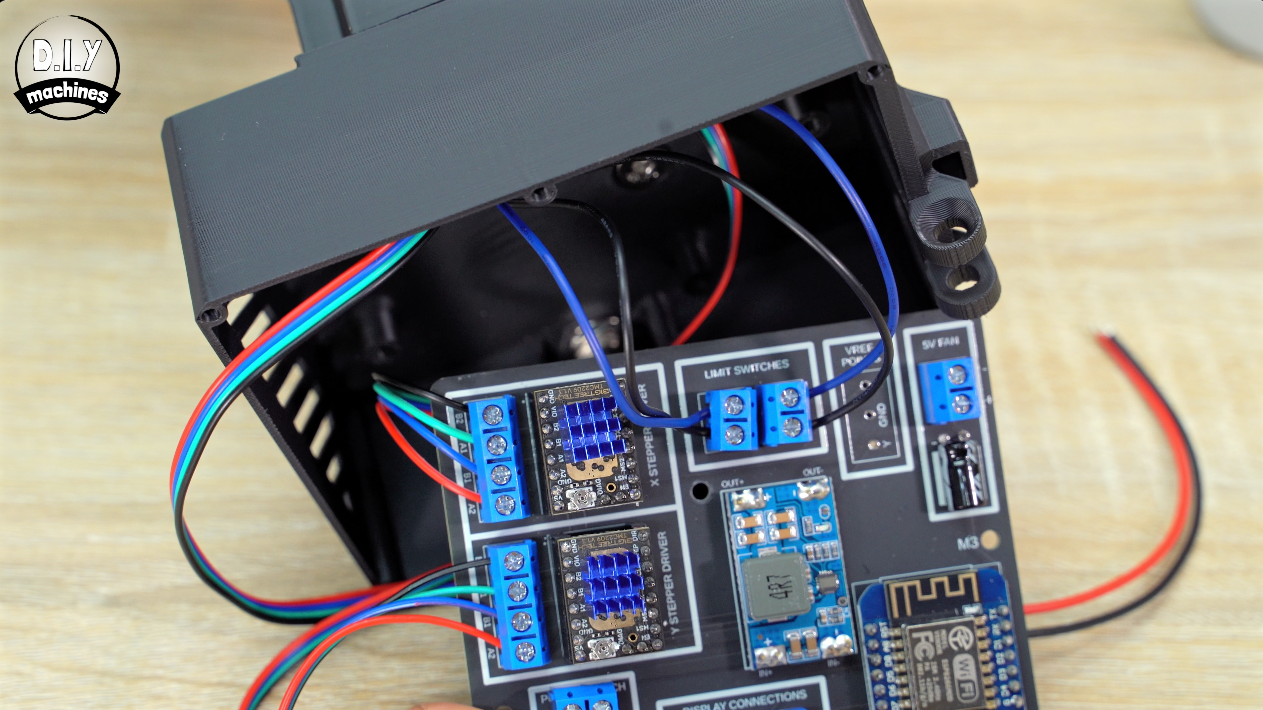
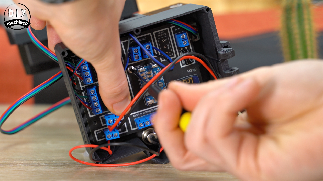
Then after ensuring no power is connected. Connect the wires from the DC barrel to the connection at the bottom of the circuit board double checking the polarity. Positive on the left, negative on the right.
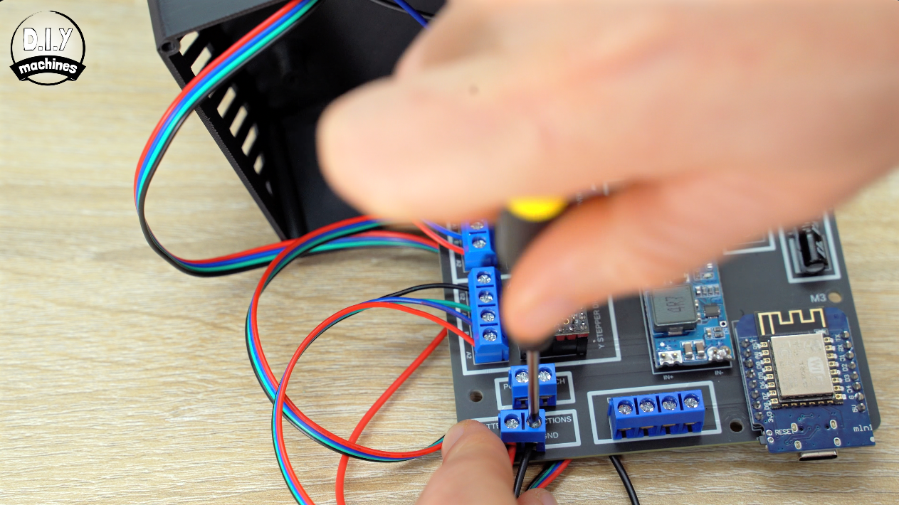
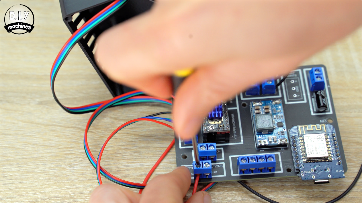
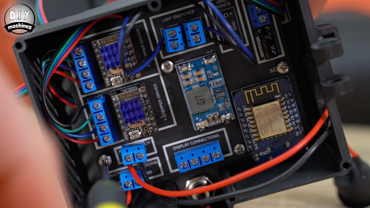
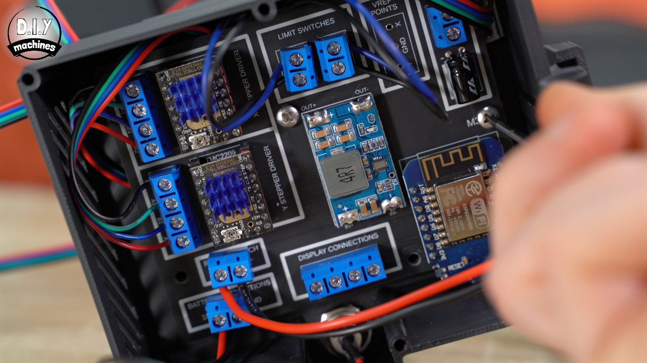
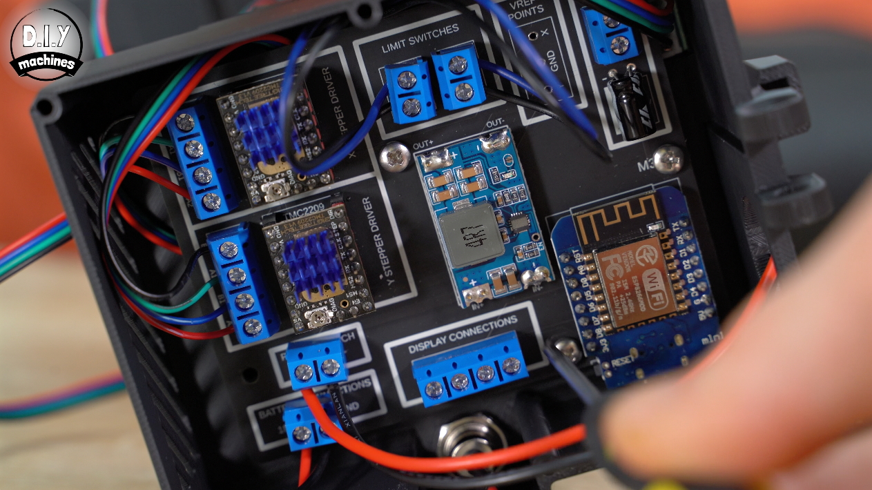
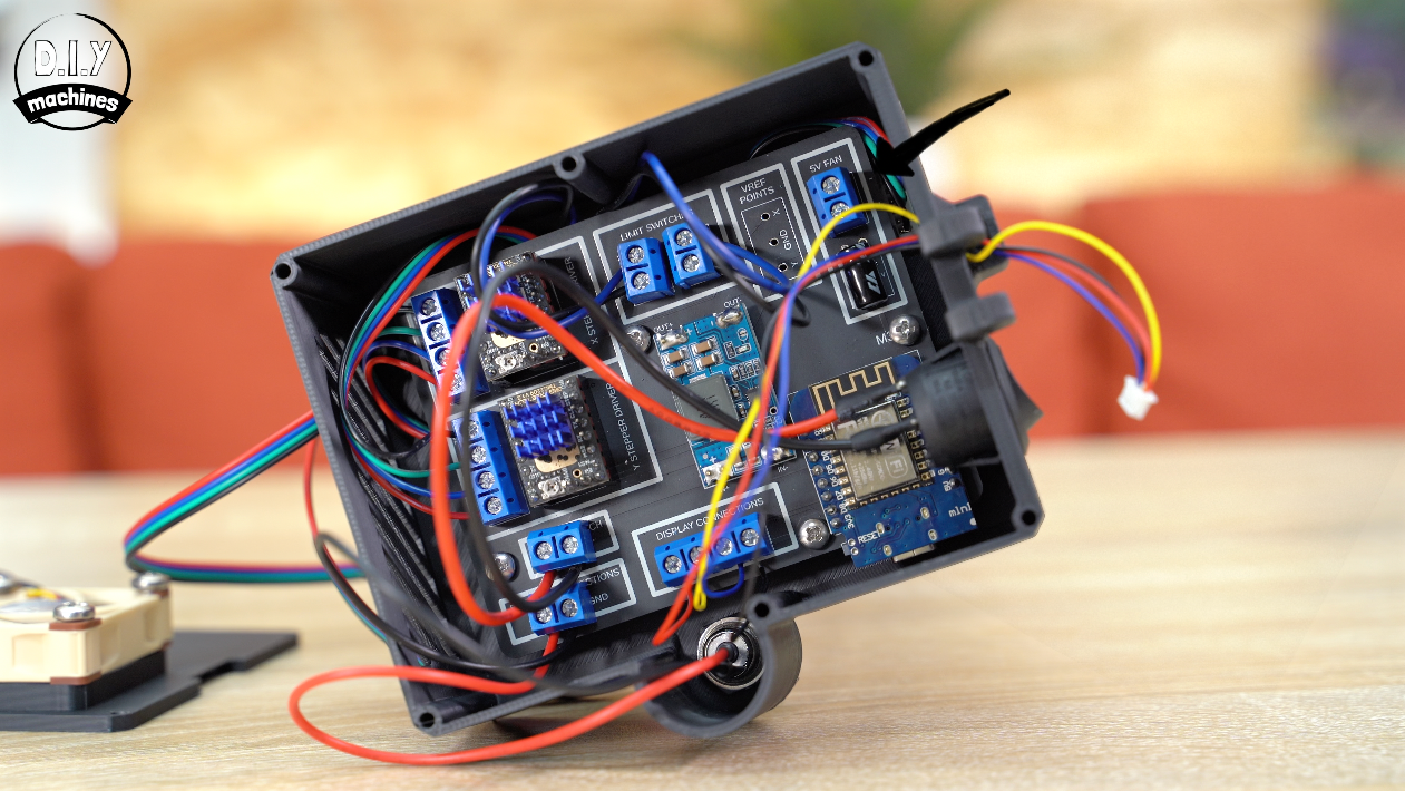
So far your board should look a bit like this:
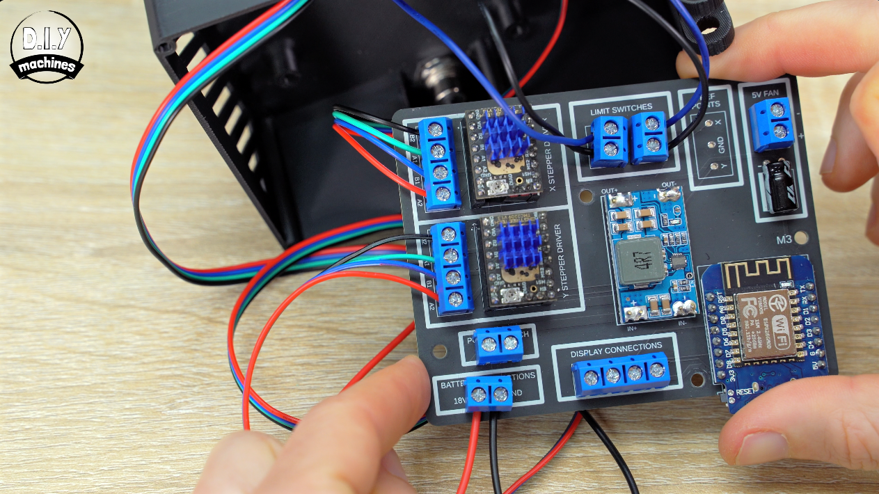
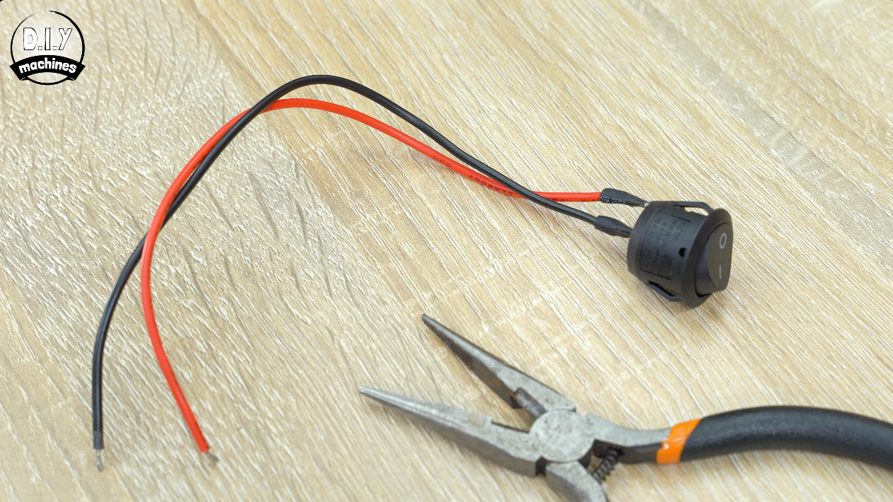
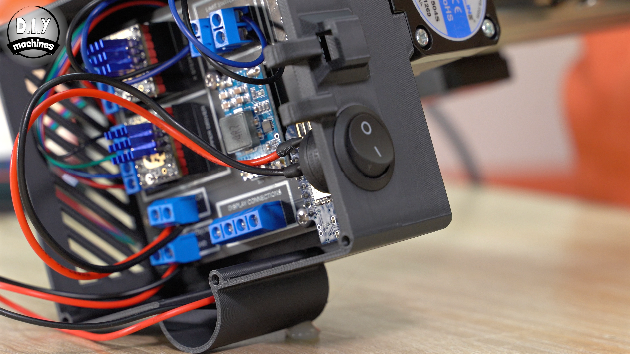
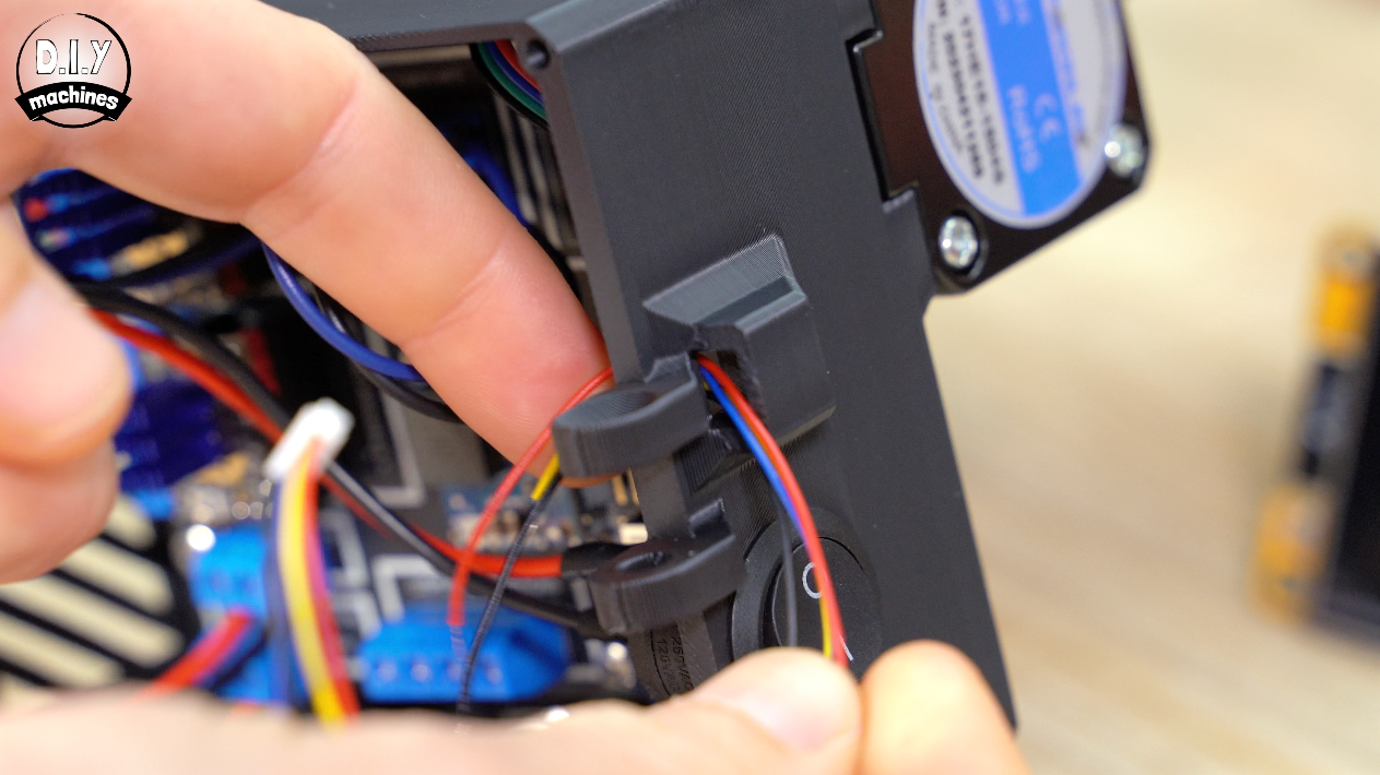
Pass the power switch through the enclosure, but don’t push it into place just yet as it will get in the way of inserting the PCB into the housing. For now connect its wires to its point on the PCB. Polarity does not matter here.
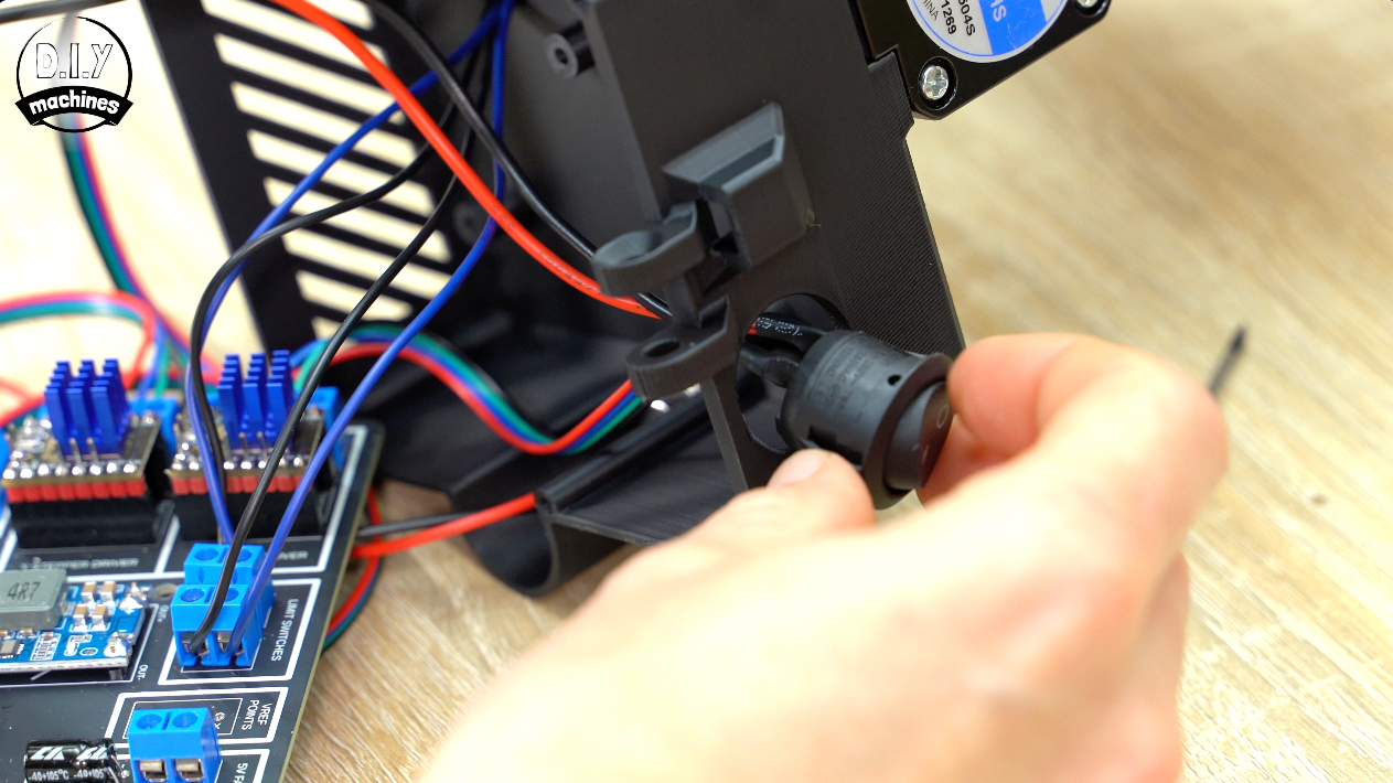
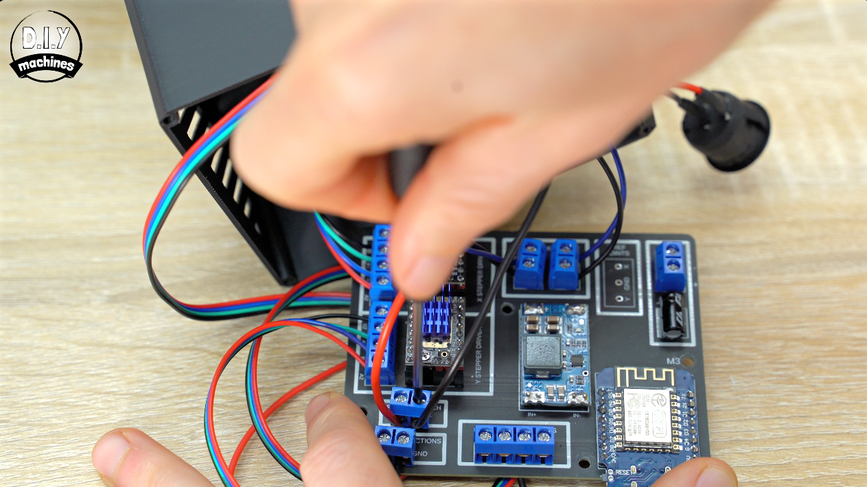
Before we bolt down the PCB, we can pull the excess wire going to the Y axis stepper motor out through the housing towards the aluminium extrusion.
Use four M3x8 bolts to hold the PCB in place. Then pop the power switch into the wall of the housing.
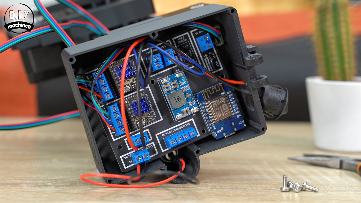
Touchscreen Wires
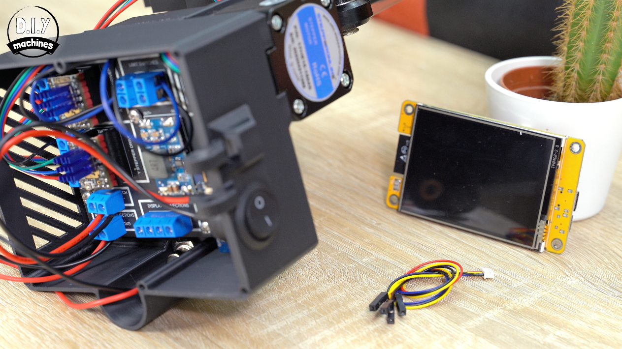
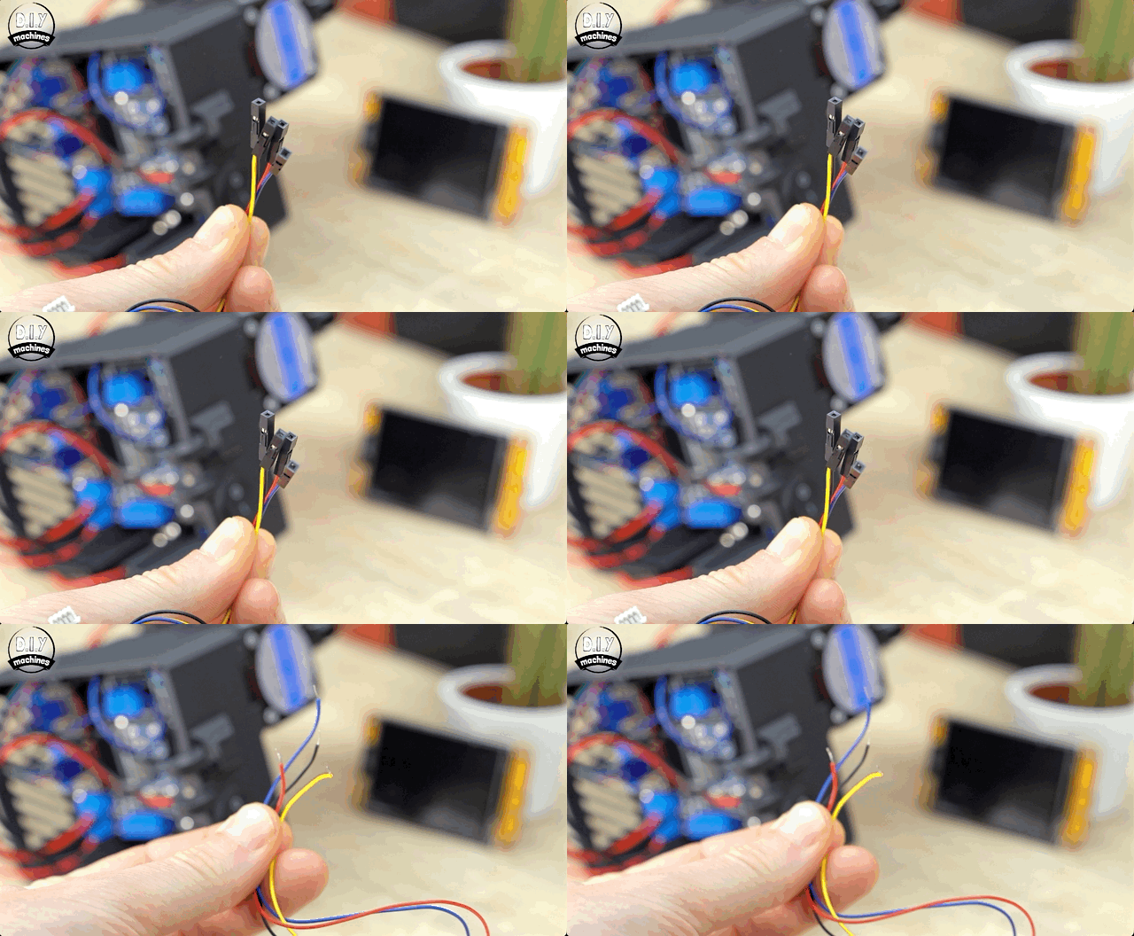
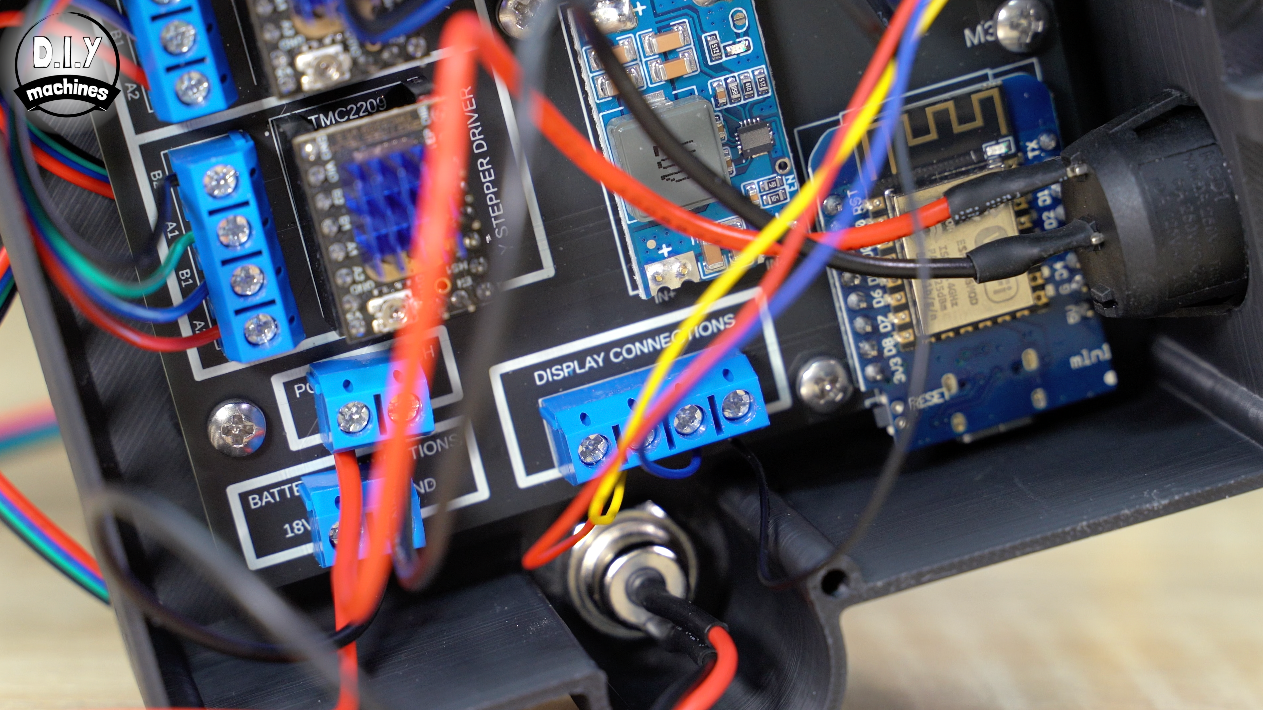
Now we will take the connection lead included with our touchscreen, pass it through the opening adjacent to the hinges and connect them to PCB at the botom centre.
From left to right it should go red, yellow, blue and black.
Lid (and optional Fan)
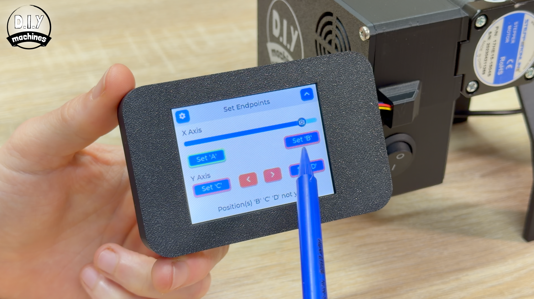
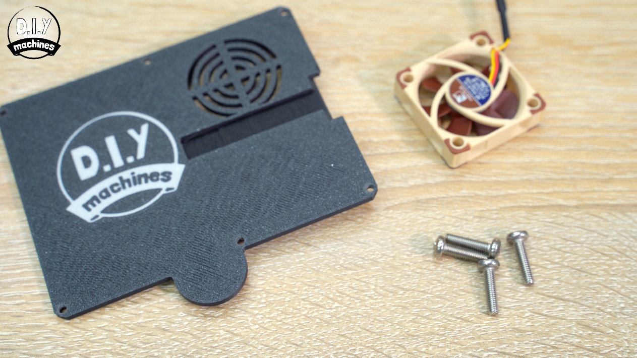
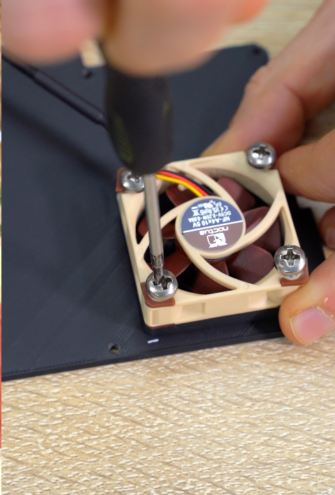
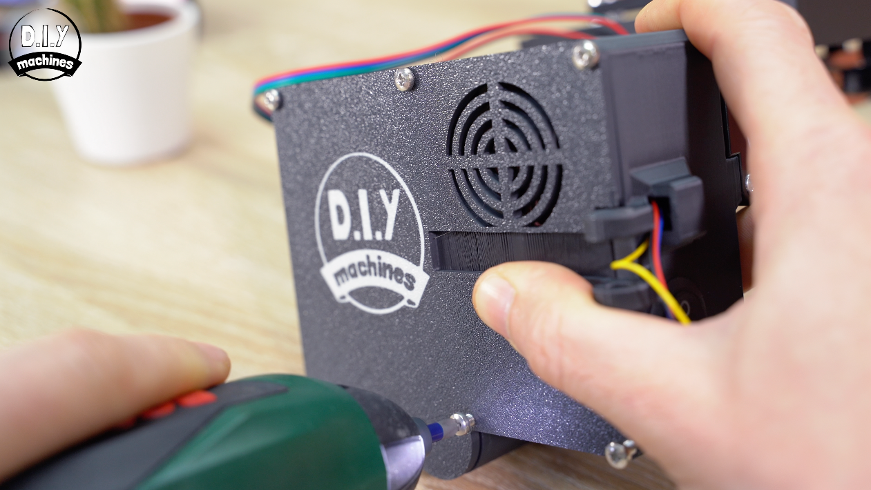
If you will be using the slider in a hot environment, with intensive high speed movements for longer periods of time you can install a 5v fan by connecting to the two terminals at the top right, and screwing it to the inside of the enclosures lid like so.
The lid is then secured with six m3x6mm boxlts.
Touchscreen Assembly
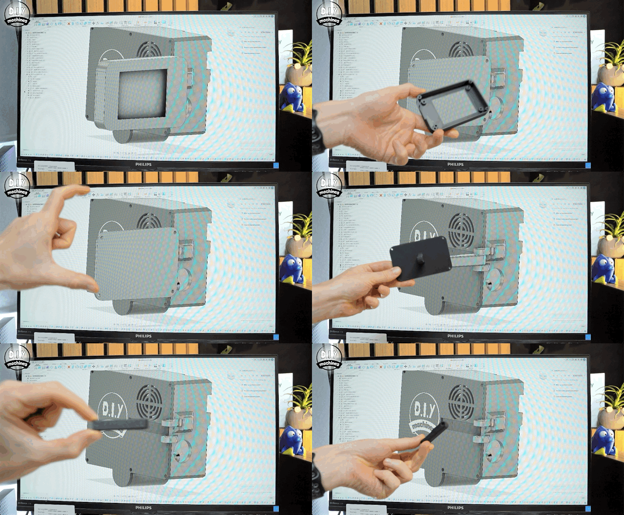
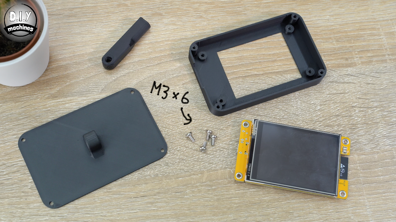
For the touchscreen we need three more 3D prints. ‘Screen Front Cover’, ‘Screen Rear Cover’ and ‘Screen Arm’.
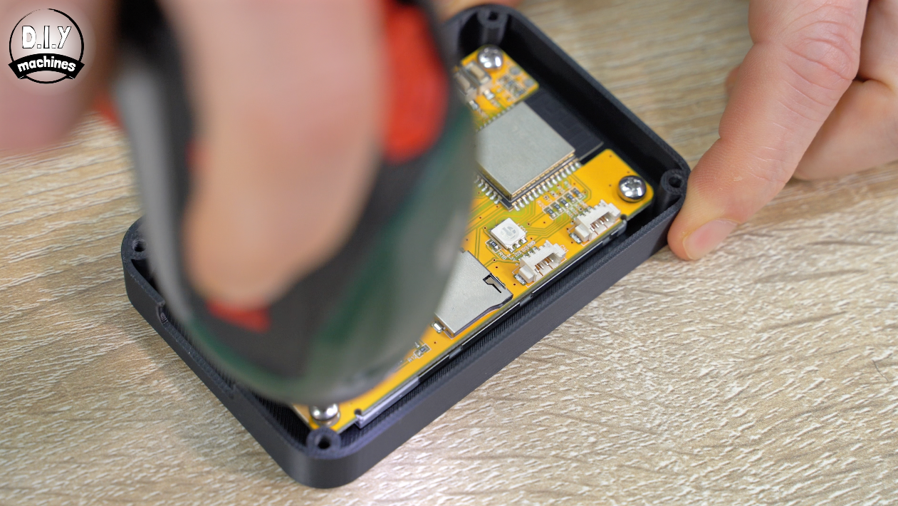
The touchscreen is attached to the front cover with four m3x6 bolts. The rear cover is attached with another four bolts.
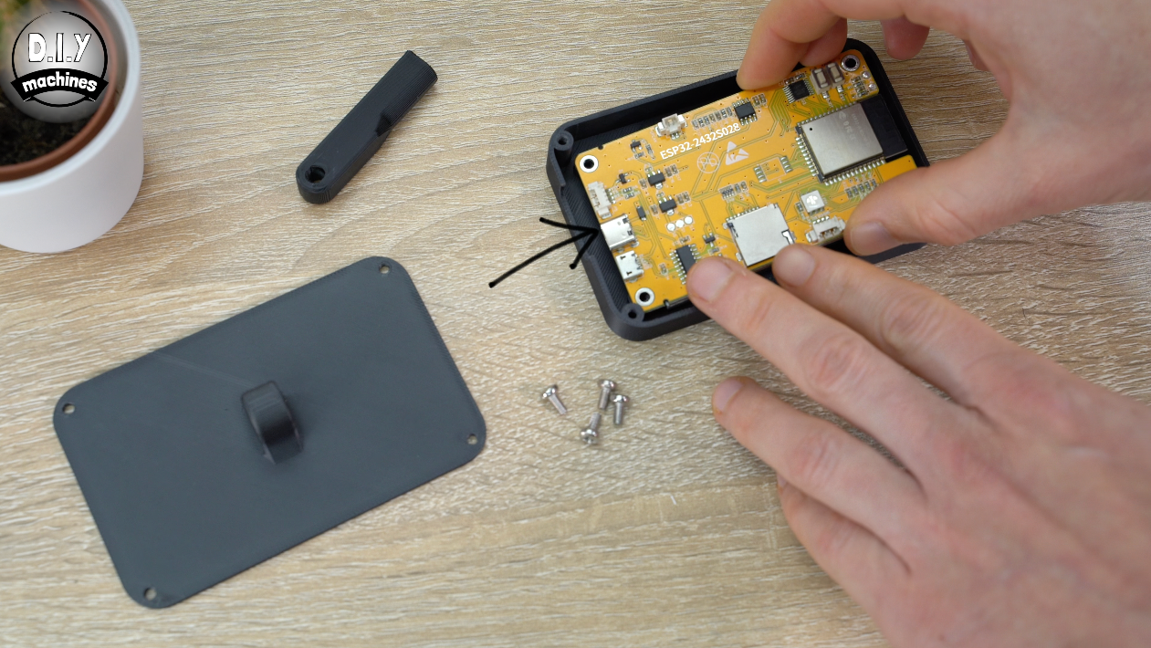
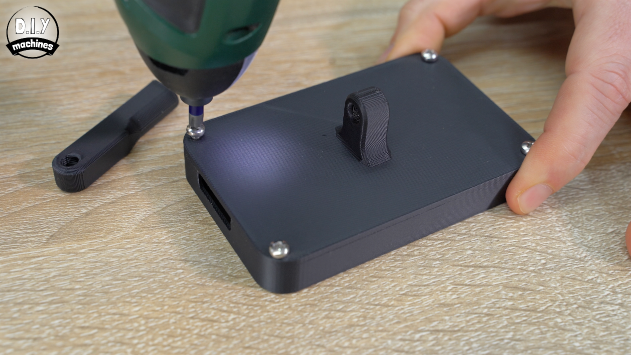
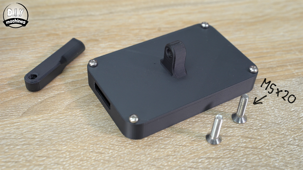
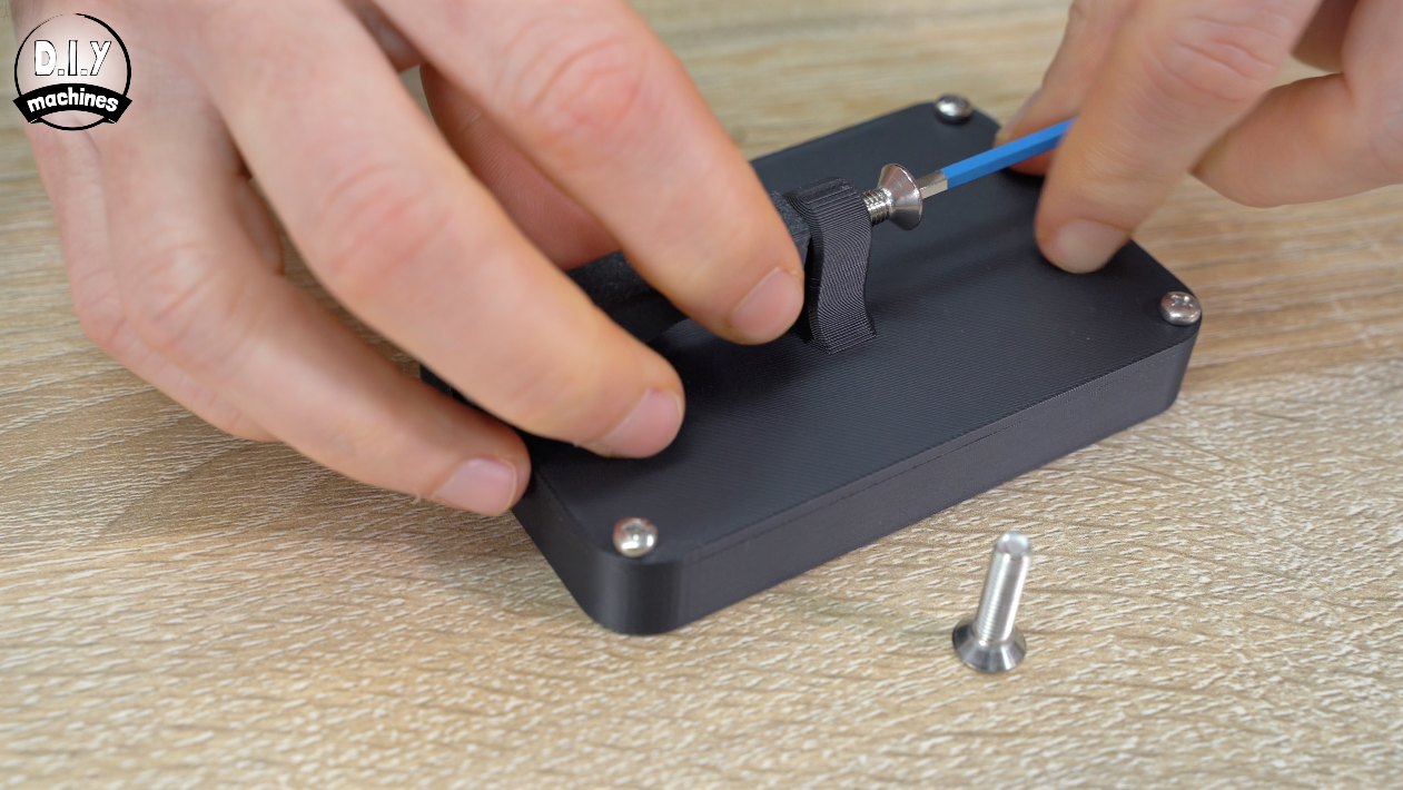
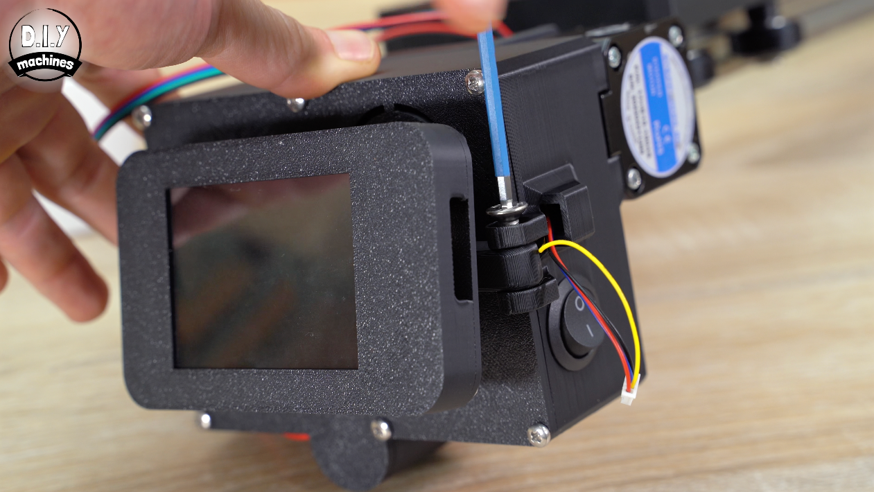
An M5x20 bolt attaches the printed arm to the rear of the screen on the same side as the open ports. Tighten it gently so that the flat face of the arm faces away from the screen. This will help it fold flat against the electronics case. Then another M5x20 attaches the arm to the hinges.
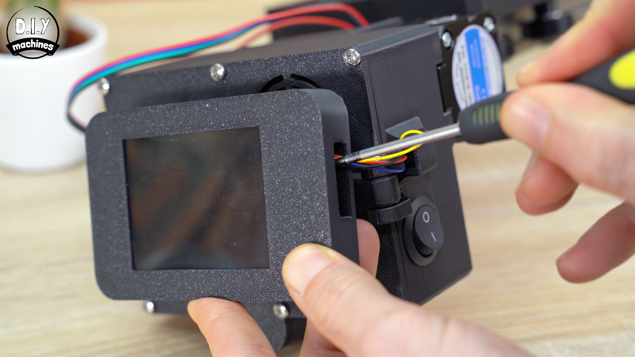
You can then connect the data and power cable - you may need to use the help of a tool to push the connector in properly.
Touchscreen Programming
The software is on my Github page and is the same set of files you downloaded for the Wemos D1 earlier. I’ll guide you through updating it now - let’s take this to the computer.
Connect the touchscreen to the port on it’s side with it’s included USB cable to your PC.
Whenever you would like to upload code to the Cheap Yellow Display you need to disconnect the serial connection to the Wemos D1 (that is this colourful cable going into its side). This is because we’re using the same wires to talk to our D1 Motion Co-processor that the computer used to talk to the CYD when programming it. If we leave the D1 connected the messages on the serial line get confused and we will not be able to program it using the Arduino IDE.
Open up the projects GitHub page, then download a ZIP of the code fi you don't already have it.
In the downloaded files open the folder ‘TouchGUI-CameraSliderV1’, then ‘eez-build’ and open the file ‘eez-build.ino’
Next we’ll check the Arudino IDE is working in the correct Sketchbook location so it can find all the correct libraries included in your download.
Open the IDE settings and browse for a sketchbook location. Browse for the same folder we just found and opened our ‘eez-build.ino’ file in and press ‘Choose’ and OK.
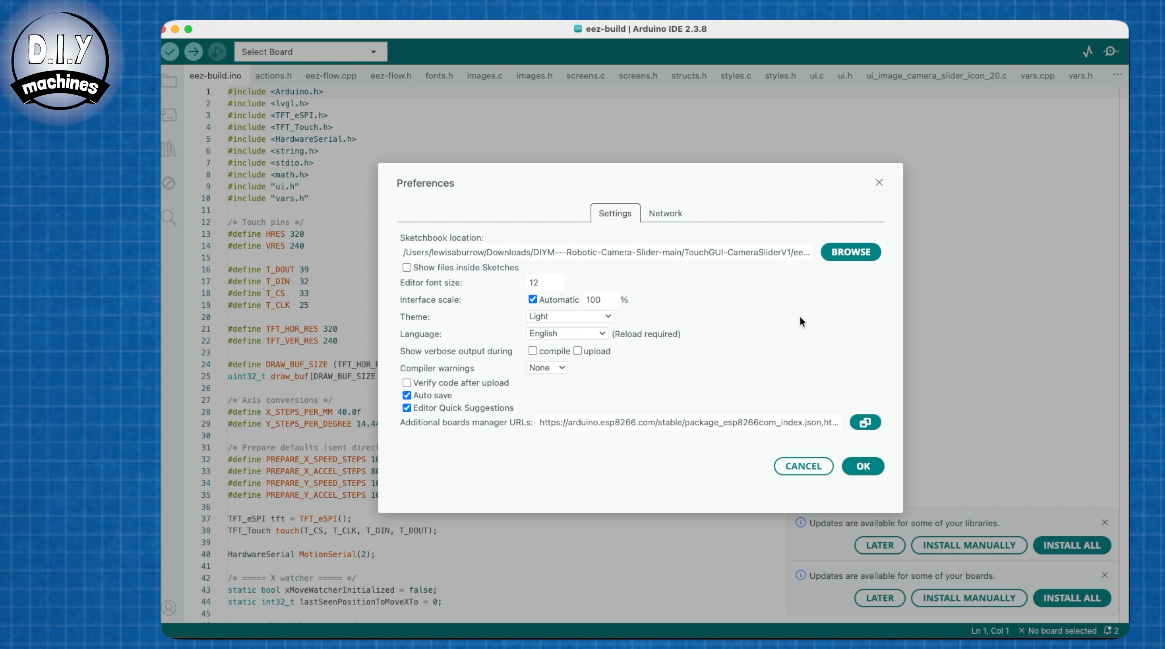
Now when you open up the library pane on the left , and set the type to ‘Installed’ you should see the same three libraries as mine here. Some may advertise an update is available, it’s best not to as I have not tested the projects code on any newer versions of the libraries which may have been released since I created this project.
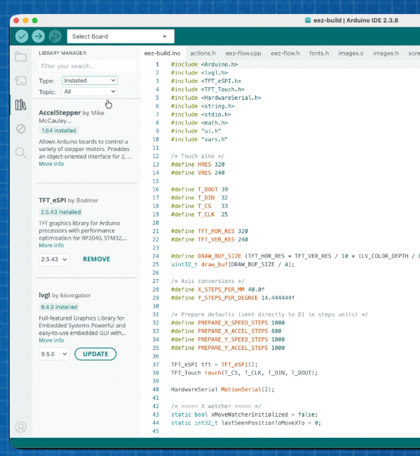
To upload it to your screen, select the port from the drop down menu and set the board to ‘ESP32 Dev Module’ and upload. You need the BAUD rate to be set to 460thousand and 800. And just in case you should have any other problems with your upload here are my board settings under the ‘Tools’ menu in the IDE for you to check against.
And please don’t forget the code will not upload if you have the rest of the project connected.
After the code is uploaded we can re connect the display to the rest of the projects electronics.
Cable Management
To help tidy the Y stepper motor’s power cables we can 3D print some cable management covers, they’re available in
a variety of lengths.
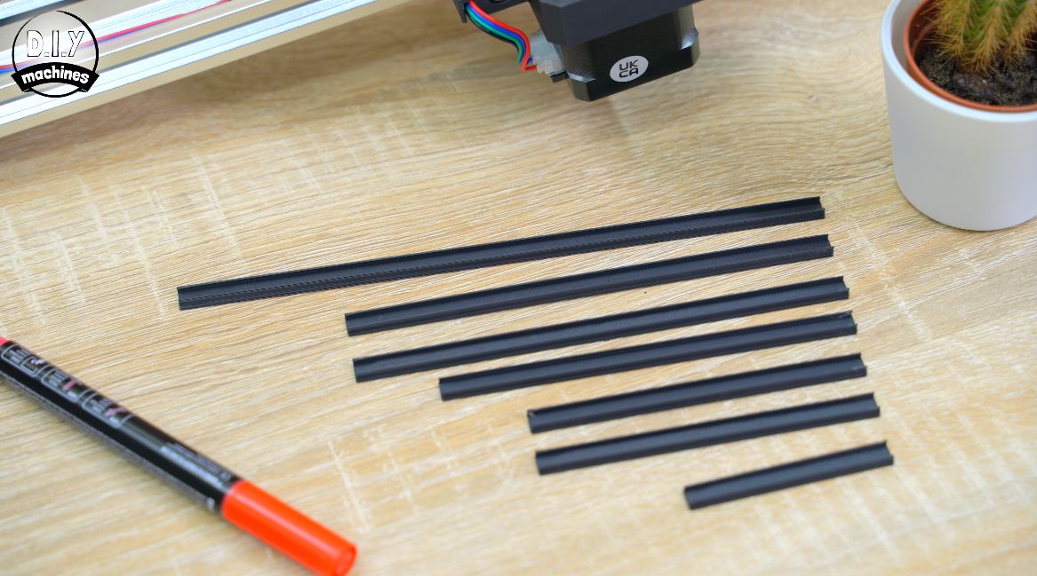
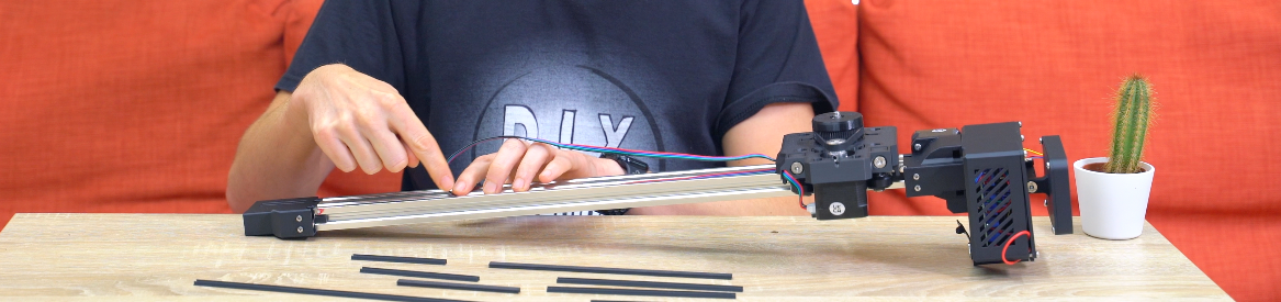
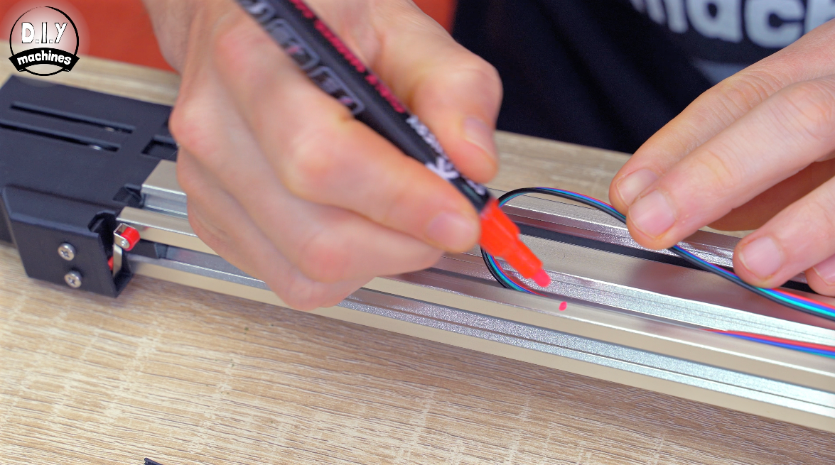
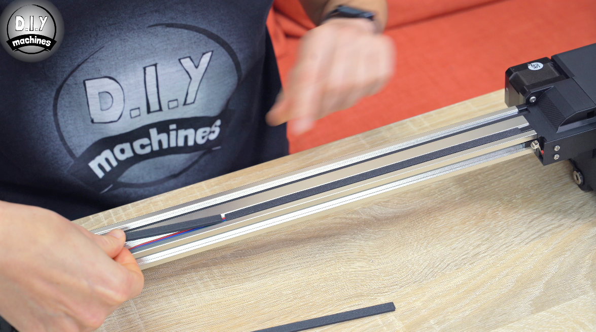
To fit them you will want to move the X axis closest to the electronics, and then to have enough covers in place to run between the electronics housing up to the cable whilst allowing it to turn back on itself and still reach the cameras platform, lay the cable down flat and just short of where it loops on itself add a temporary mark (could be pen or tape) and insert covers by pushing them into the extrusion up to this point.
Ryobi Battery Pack Adapter
If you’re going to be powering yours with an 18v DC power supply you can do that now with the barrel connector on the electronics housing. If you’ve not made it already, I’ll show you now how to make the Royobi battery adapter.
You may or may not have noticed over my videos and Instructables that I am mainly a Bosch power tool person and as such have a lot of Bosch Batteries, so why for this project did I opt for a Ryobi battery system?
There are a few reasons but the main ones are that the terminal layout is simple, and I believe they have built in over current protection, over temperature cut off, over discharge protection and cell balancing. I’m not saying Bosch is unsafe - but Ryobi is just easier for self made projects like this.
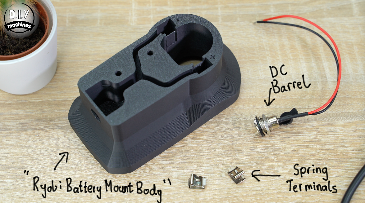
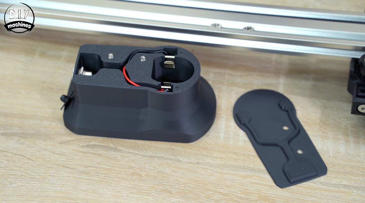
To assemble this you’ll need to print the ‘Ryobi Battery Mount Body’ and its lid.
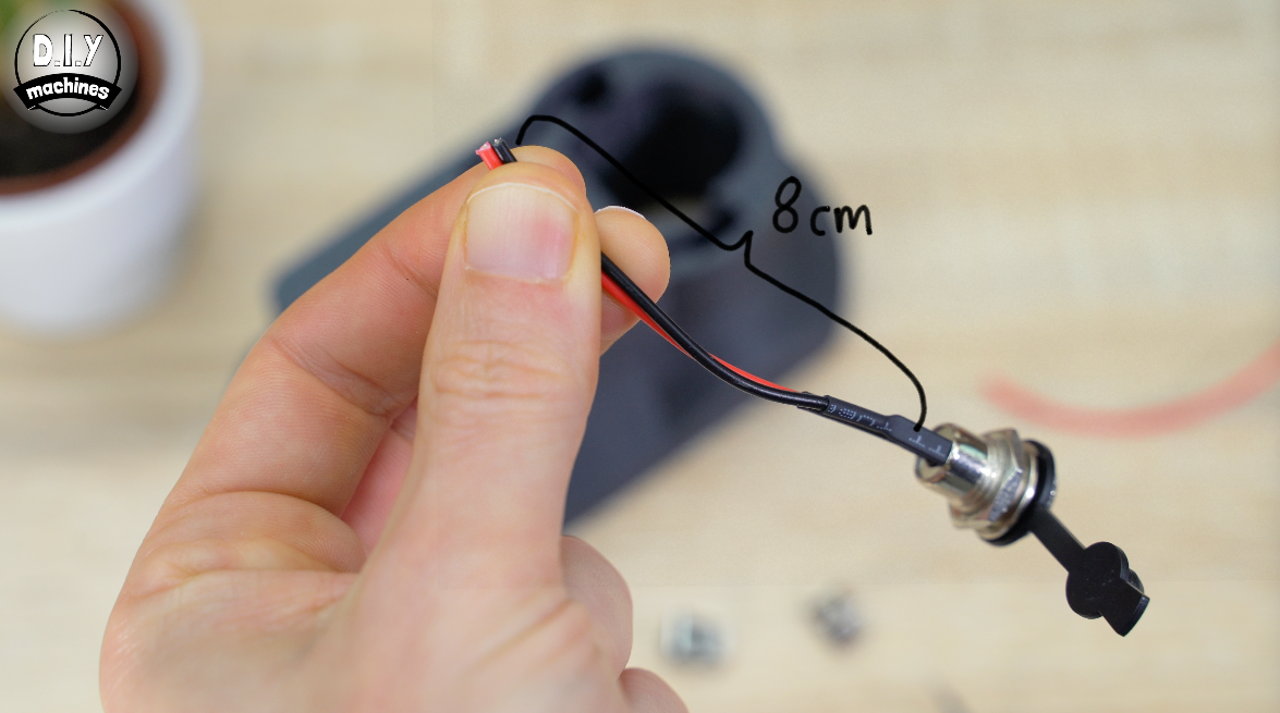
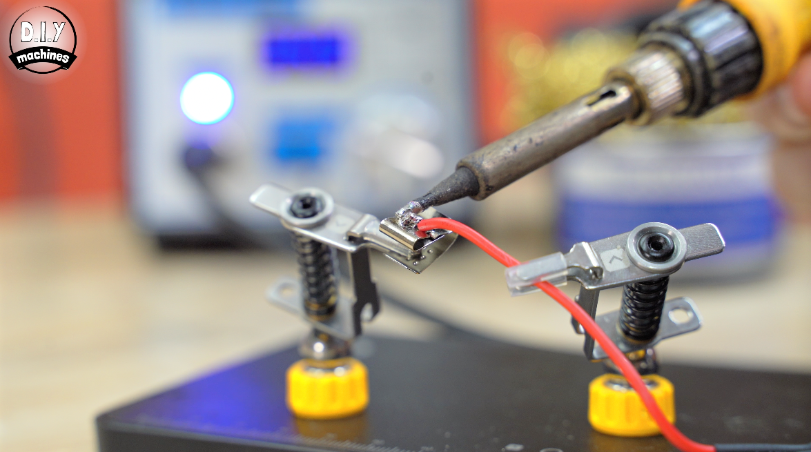
Cut the wires down to 8cm in length on your female barrel adapter and then we’ll solder on the spring terminals. One to each wire.
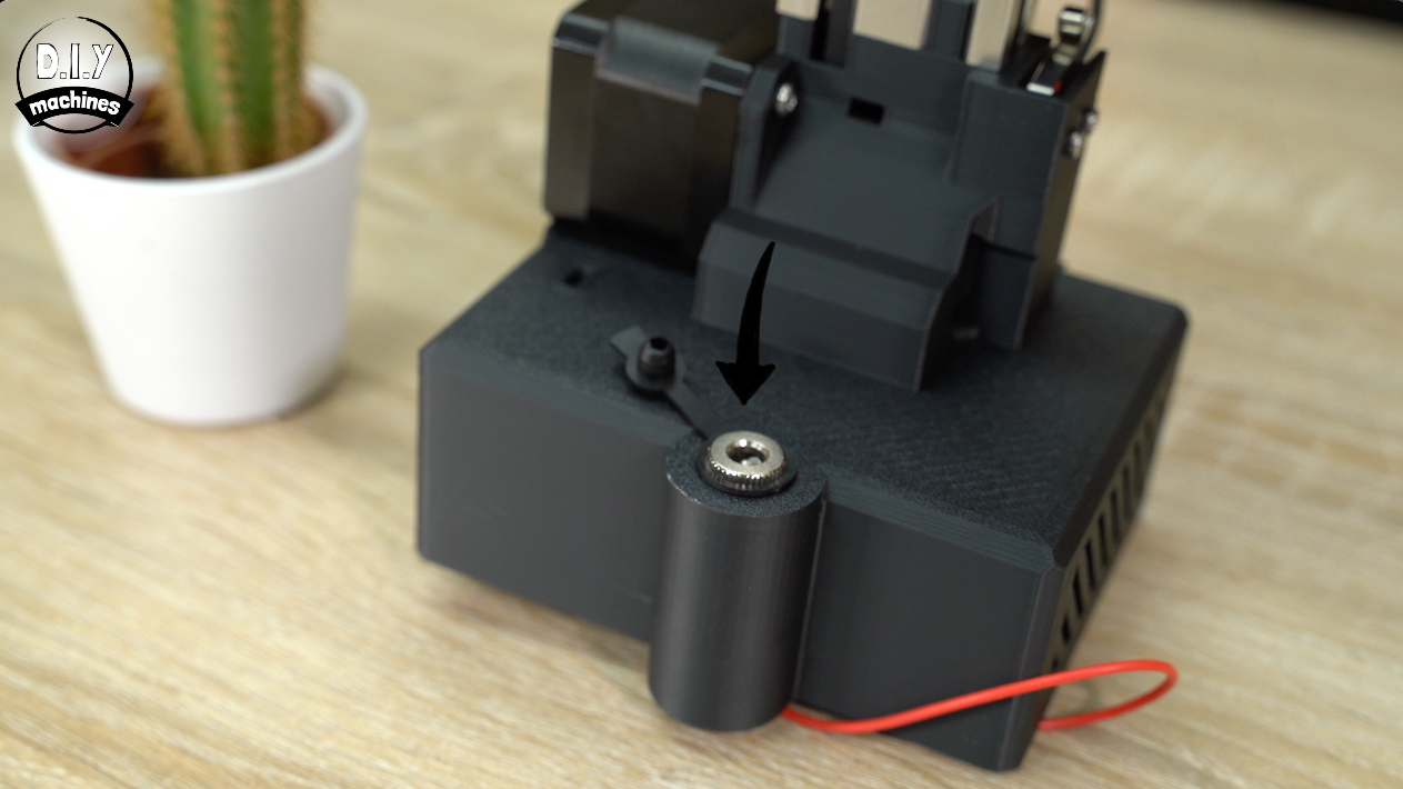
We can then carefully thread these through the hole and mount the barrel connector in place with its included washer and bolt. (You can just about squeeze these over the spring terminals one at a time).
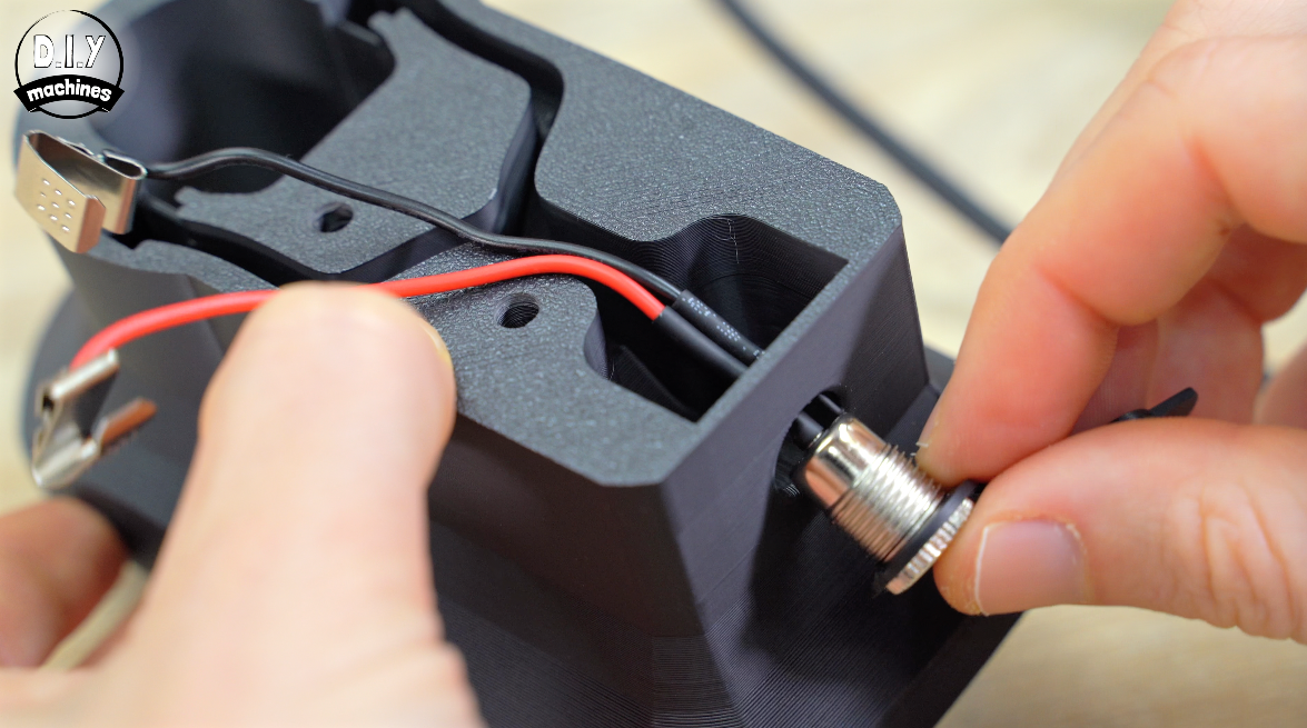
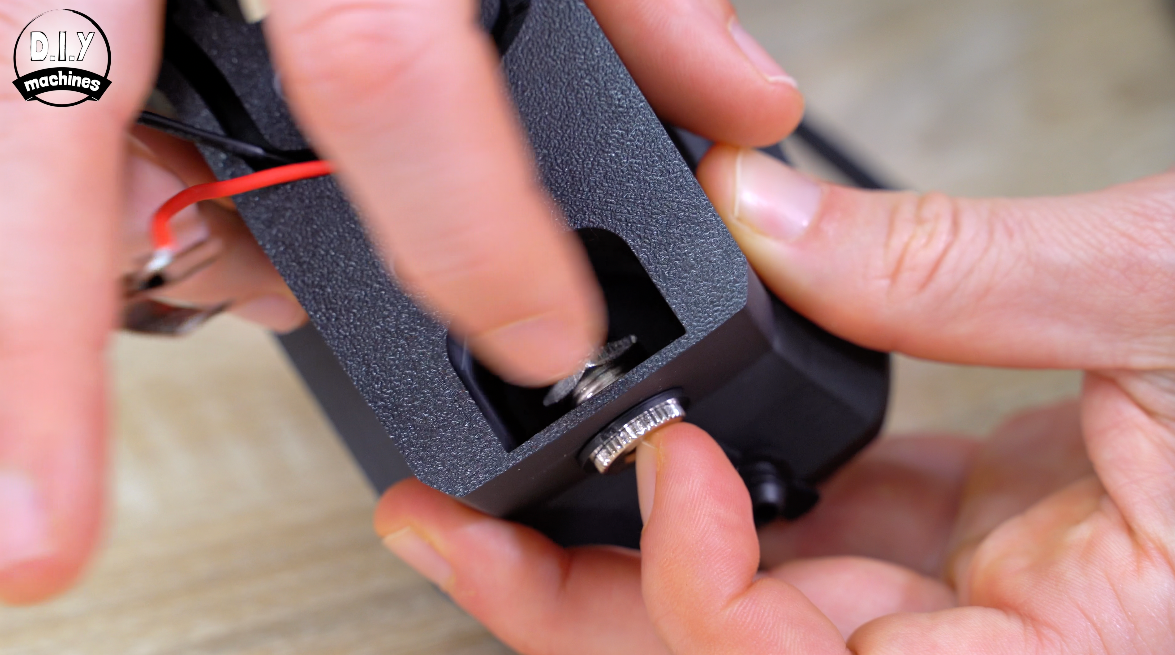
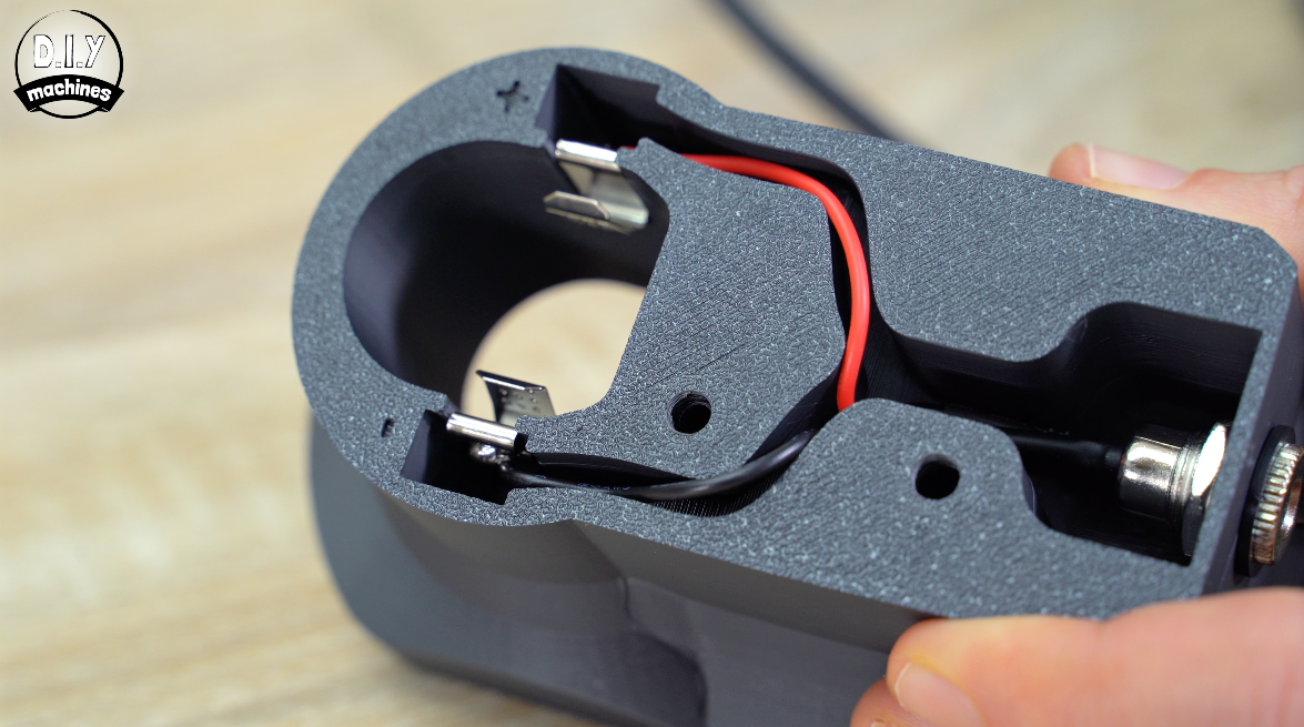
You’ll see that I have marked on the 3D print which side is for the positive terminal and which is negative, slide the spring clips onto their correct positions over the internal ridges double checking you have the red wire on the positive side and black on the negative.
Test your battery now, it should fit with a satisfying click. :)
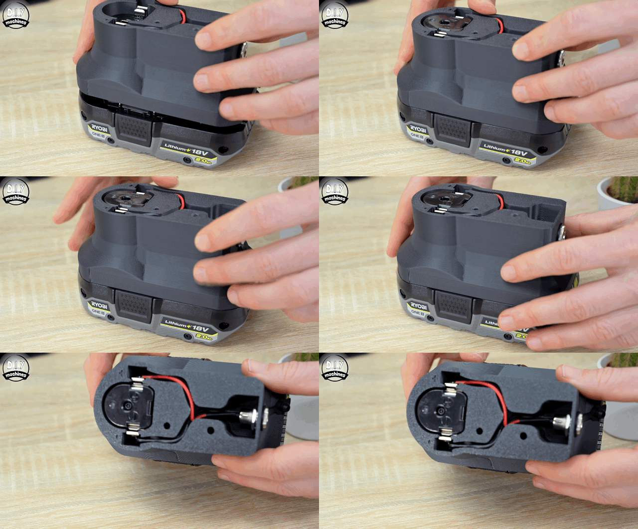
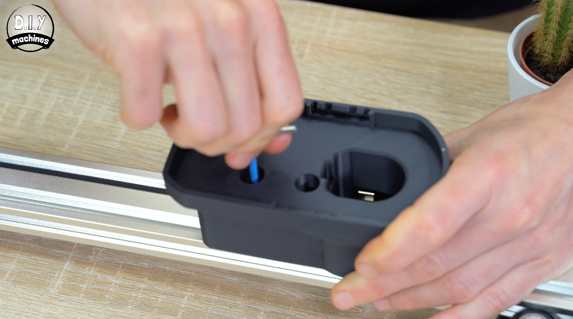
Let’s attach it to the extrusion, remove the battery and pop a couple of M5x14 countersunk bolts though the main body (from the battery side) and the 3D printed lid.
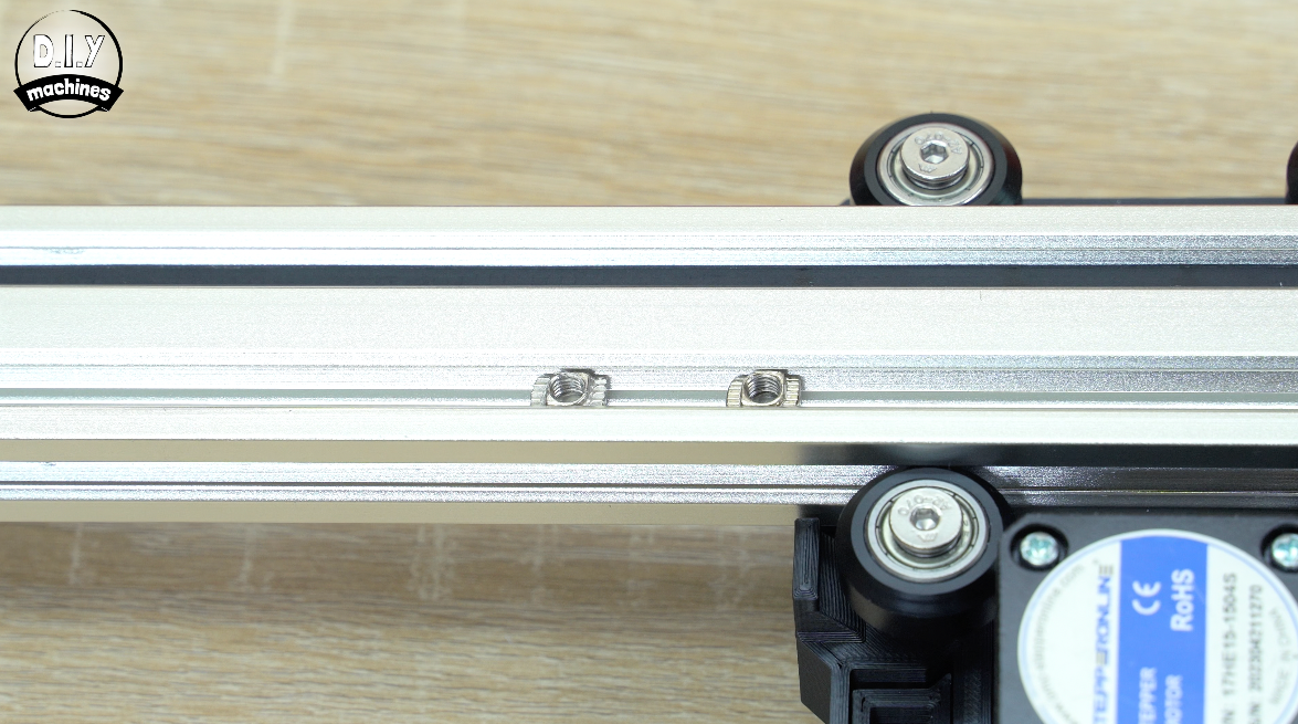
‘Drop in’ a pair of M5 T Slot Nuts into the underside of the aluminium extrusion. Use an Allen key to tighten down the bolts in our 3D print into the T-nuts until it locks the battery mount to the extrusion.
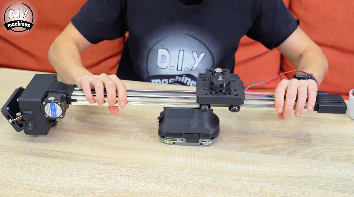
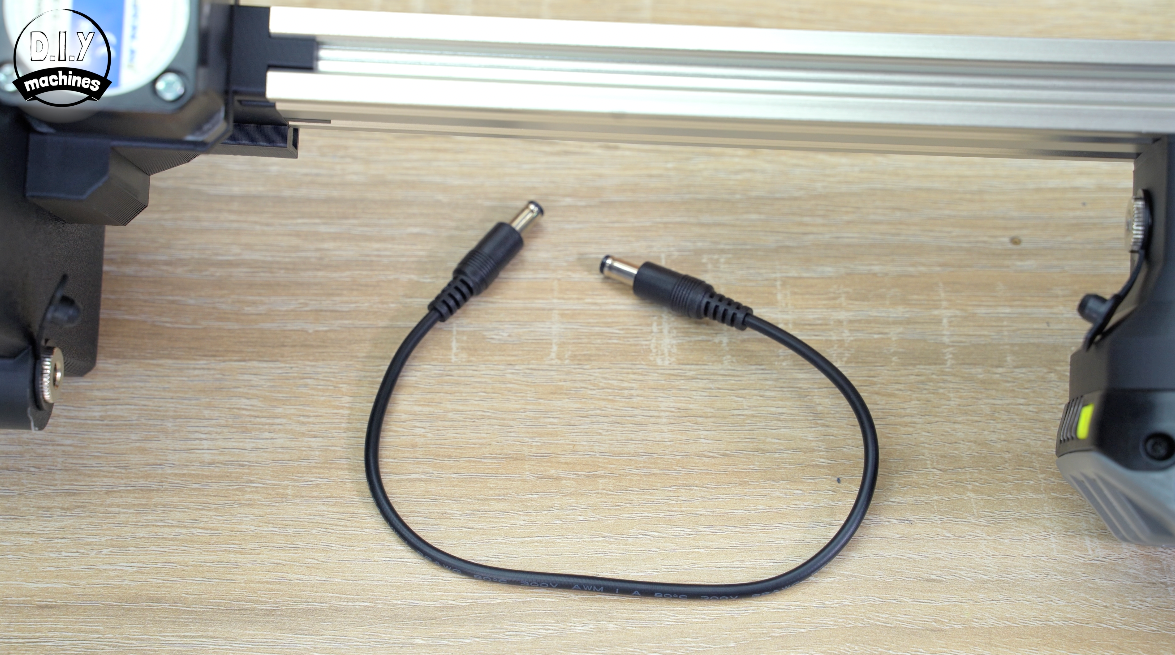
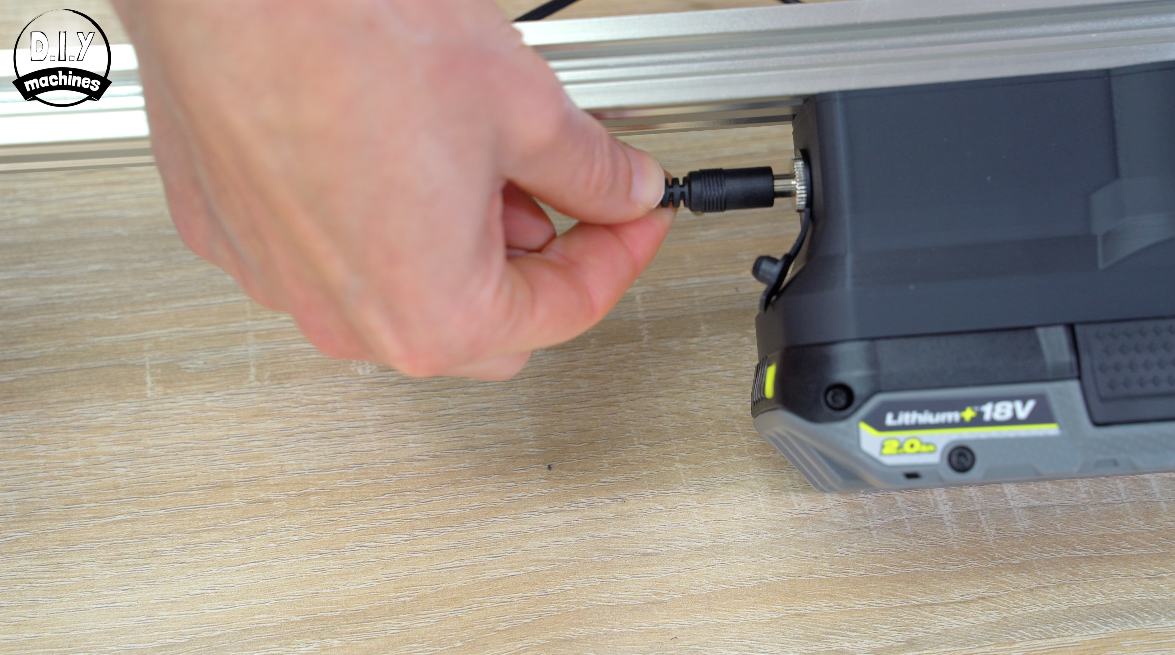
To connect it to the electronics enclosure you can either buy a ready made DC barrel to barrel cable or make your own with two male plug and two lengths of wire. Connect the same terminal on each plug to each other.

Testing & How To Use
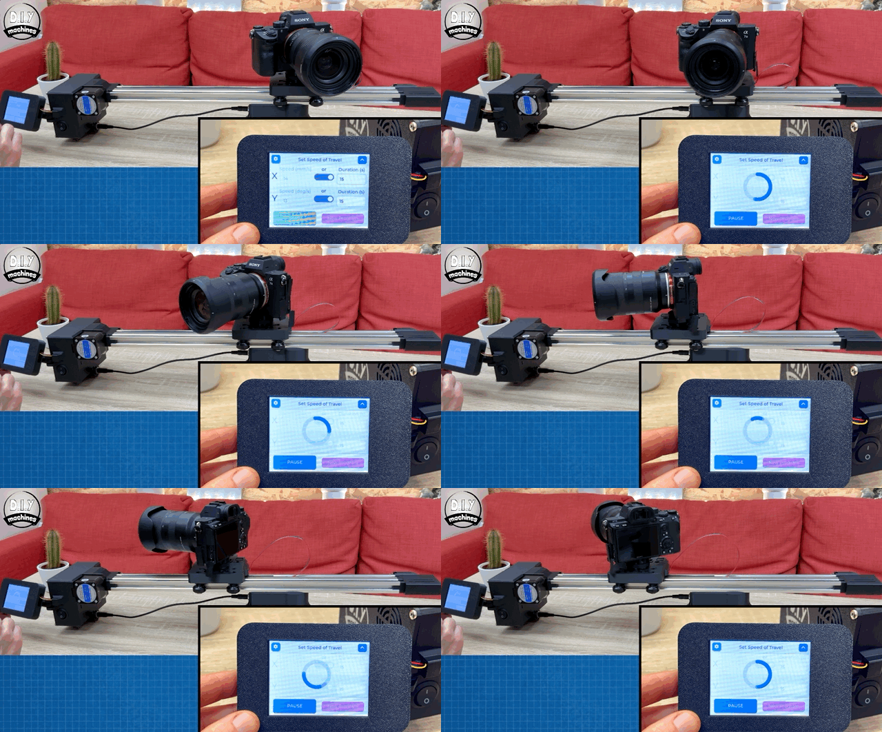
Now showing you how to use the slider is one which is not super-critical to help you build one of your own. As this written guide is rapidly growing in length - I want to keep it focused on the build itself. So, to that end (and because it's much easier to show you in video) I will refer you to the second video 8:58 into it. (embedded at the top of this article and available here: https://youtu.be/aUi5cK1G4hc)
Mounting: 3D Printed Legs
As promised earlier in the guide, let’s now mount this slider on something more appropriate rather than just propping it up. You have two main options. You can either 3D print legs or a universal photography tripod interface.
There are two sizes of legs available to download and print depending on your needs and size of battery pack if you’re using one.
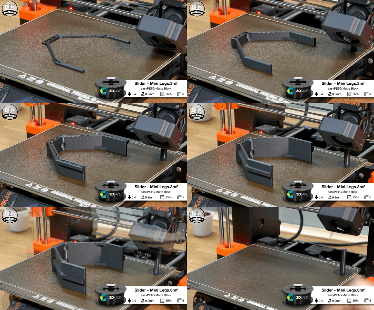
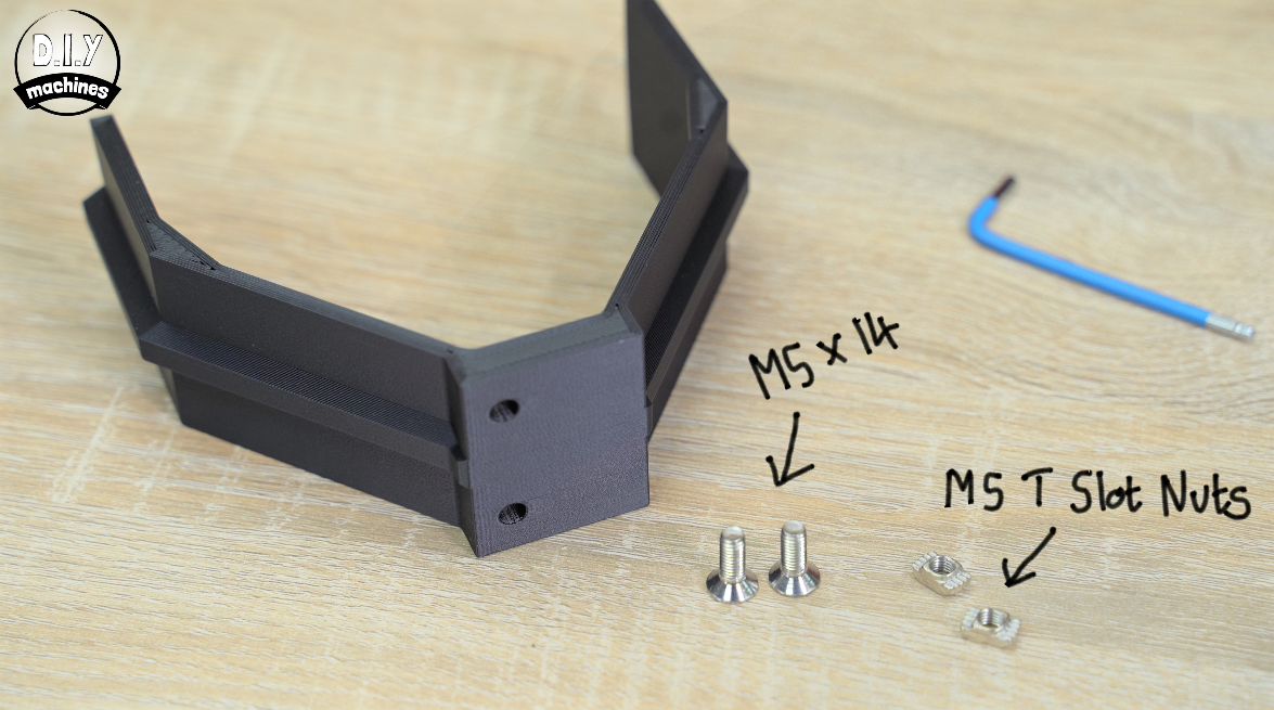
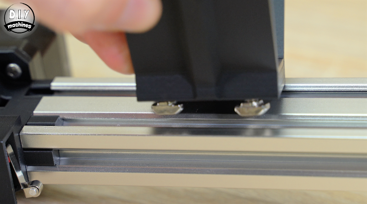
These are both fitted in the same way as the battery. You’ll need two M5x14 bolts per leg, and two more t-slot nuts per leg.
This time you can try placing the nut loosely on the bolt after screwing the bolt all the way through the leg. This is then attached directly to the extrusion.
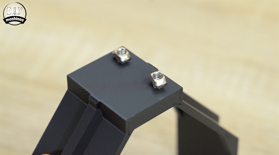
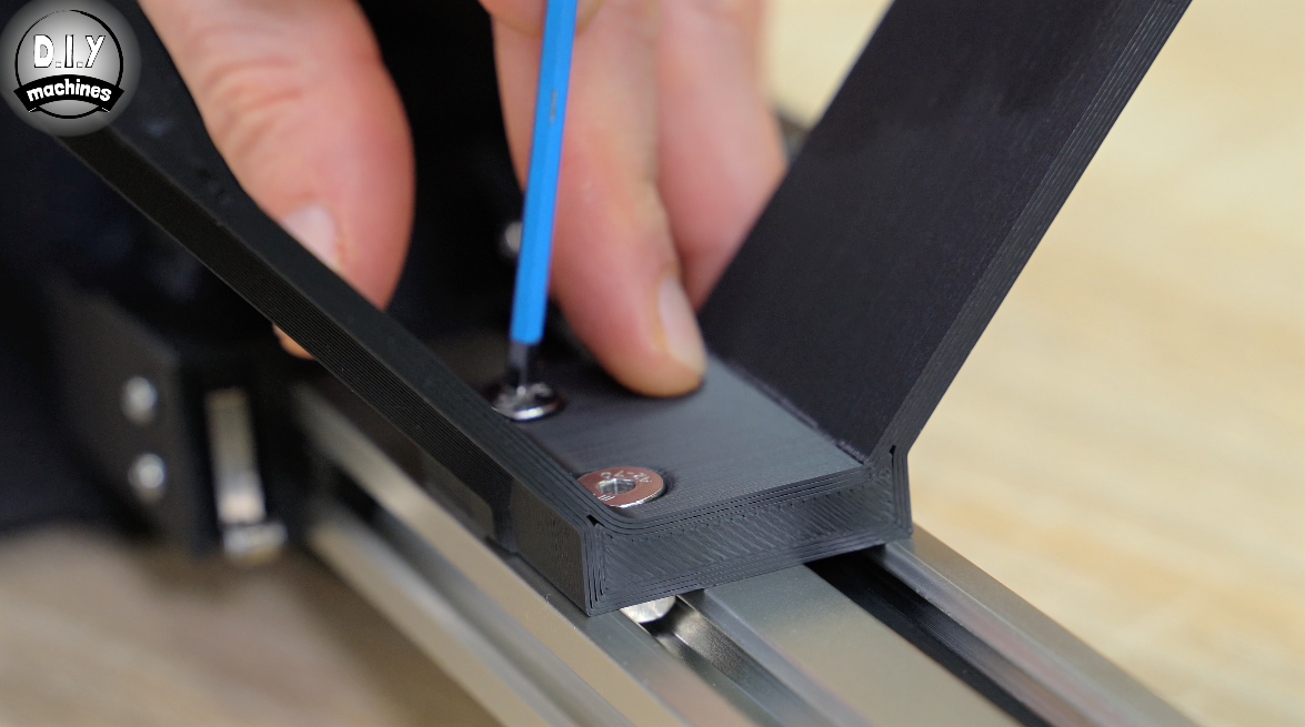
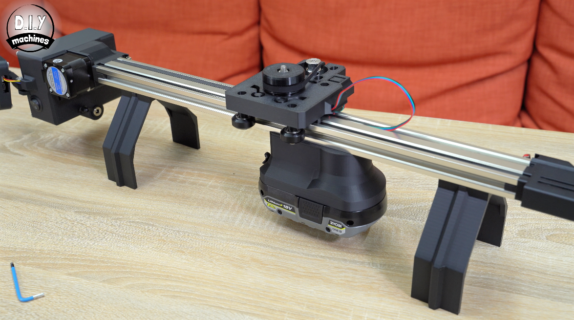
Mounting: Universal Tripod Interface
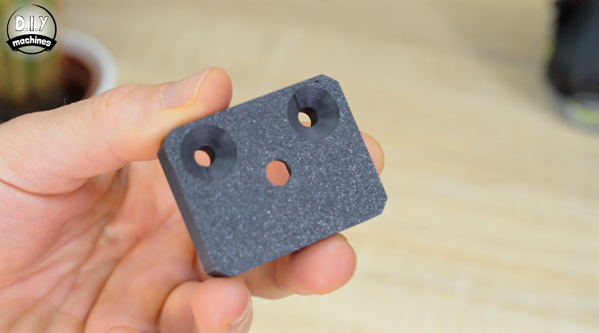
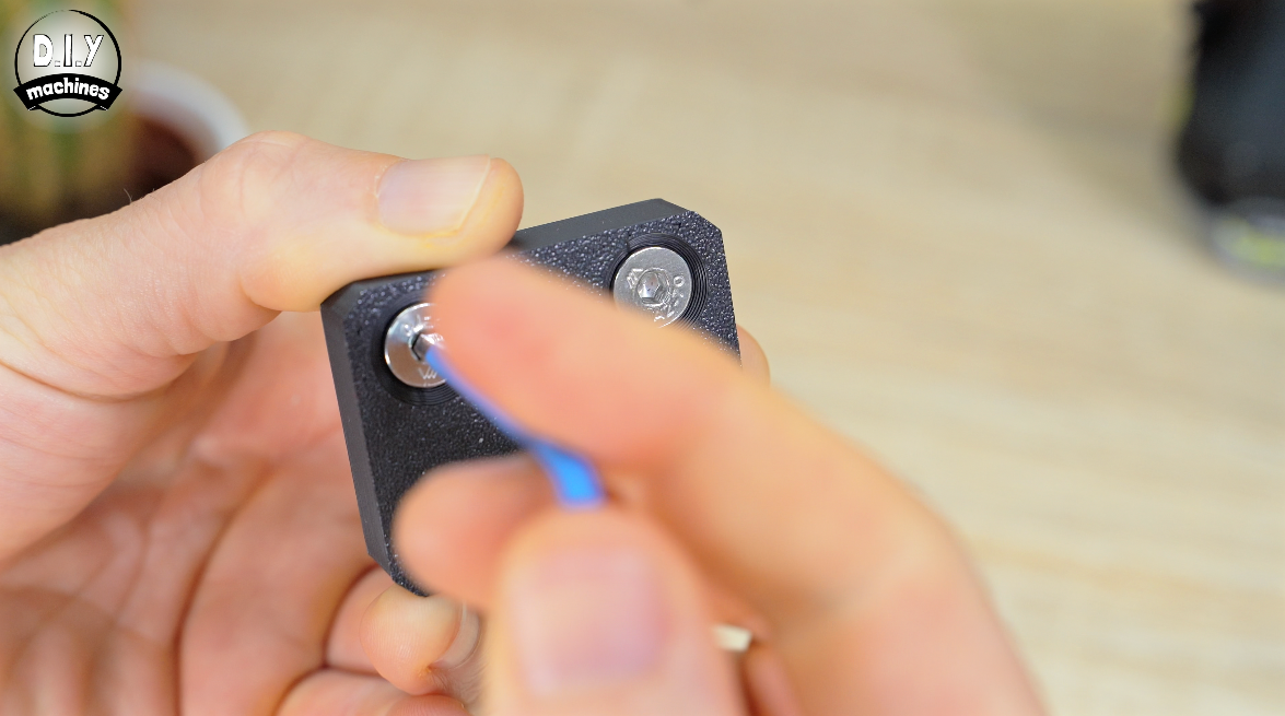
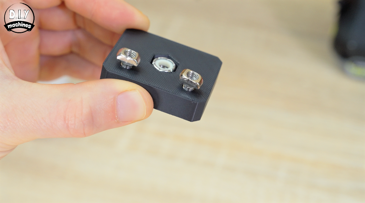
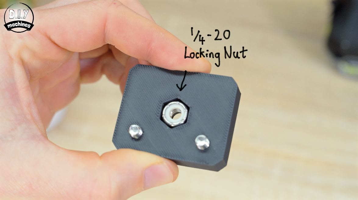
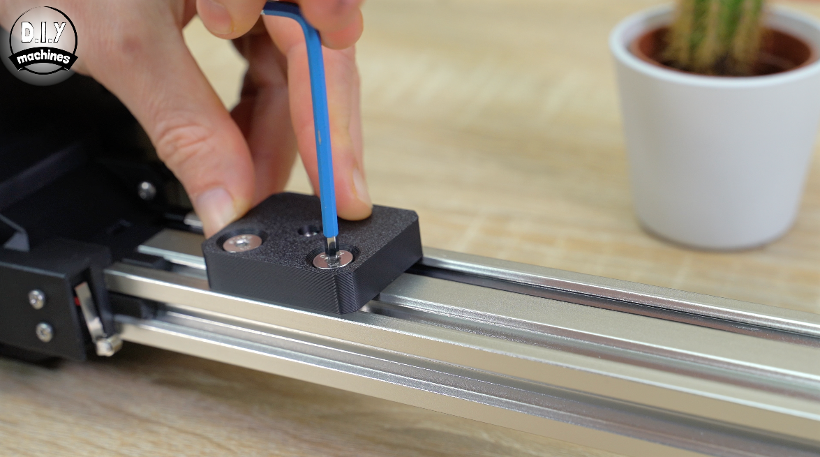
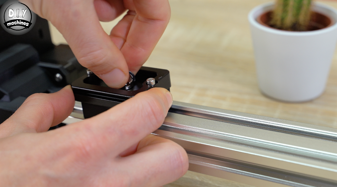
The tripod mount is fitted in the same way, but you’ll need two add a 1/4 Nylon nut into the print before fitting it.
You can then add a quick release plate to this for attaching to a tripod. Including the nut makes the connection universal and so allows you to use all sorts of photographic hardware such as ball heads.
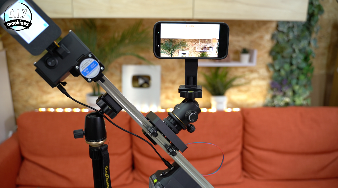
Build Complete
Congratulations on finishing your very own twin axis slider! Enjoy the fruits of your work and feel free to send a photo or video in. I love seeing what other have built.
Until the next project, do some good and ciao for now!
Lewis
Community & Help:
Discord server for this project: (A great place for questions and advice):
https://discord.gg/E7dwcw5FwR